

MAXIMISE YOUR JUNOS NETWORK WITH MPLS, PART 3: CONTAINER LSPs
As cool as RSVP label-switched paths are, they’re not perfect. For example, they don’t take you on dates, and they don’t text you memes. They don’t remember your birthday. Come to think of it, I’m not sure they even know my name. Wait, sorry, I’ve just realised that I’ve mistaken “RSVP label-switched paths” for “pop star Taylor Swift”. Why do I keep doing this?
Okay, forget everything I just said: a more real and less made-up example of RSVP LSPs not being perfect is that it can be tricky to load-balance over them.
Why? Because a single LSP is a precise hop-by-hop path. Load-balancing MPLS traffic requires at least two separate label-switched paths, which isn’t very scalable when you realise that you might need to double the number of LSPs in your network.That’s double the amount of RSVP state, constantly refreshing.
And that’s just if you limit yourself to two LSPs. In fact, you might have any number of ECMP (Equal-Cost Multipath) paths you could load-balance over. What if you want to load balance over three paths, or four? Another example would be five paths. I can’t think of a sixth example, but I can think of a seventh example: seven paths. In that situation, you need to make seven LSPs in advance, just in case you need them. Again, it doesn’t scale very well.
Oh, I just thought of an eighth example: nine paths.
Well, in this blog post I’m gonna let you in on a secret. You know: the kind of secret that is openly printed in books and on Juniper’s website. Because it turns out there’s a way we can do create these ECMP LSPs automatically. In fact, truth be told, they don’t even need to be equal-cost!
Yes, the rumours are true: we can create something called a “Container LSP”, which can then dynamically create any number of LSPs, whenever they’re needed, depending on the actual bandwidth going over the network – and then tear them down when they’re not needed. In today’s post we’re going to take a real good look at exactly how it works, and I think you’re going to like what you see!
This post is the third in a cool three-part series on automatically maximising the bandwidth usage in your MPLS network. In Part 1 we learned how to manually reserve bandwidth on an MPLS path. Then in Part 2 we learned about “Auto-Bandwidth”, where the bandwidth reservation happens automatically based on the real traffic going over the link.
In this third and final part of the series, we’re going to take all that knowledge to the next level, by seeing how Container LSPs use all that good stuff to create something really impressive. Juniper sometimes calls Container LSPs “TE++“, depending on whether it’s engineers or a sales person talking. But whatever you call it, it’s super-handy.
Let’s dive into the lab and see it in action!
HOW DO CONTAINER LSPs WORK?
In last week’s blog post we learned how to configure an MPLS bandwidth stats file, which takes regular samples of the bandwidth going over our LSPs. We saw how to use this file to find the highest bandwidth sample within a certain time period, and then get our LSPs to re-signal itself with a reservation of this new bandwidth.
We learned that if there’s enough bandwidth on the existing path, then the LSP stays on the new path. Or, if an even better path turns out to now be available, the LSP will happily go that way instead. And if there is not enough bandwidth on the current path, the LSP use our old friend CSPF (Constrained Shortest Path First) to find a path that does indeed have enough bandwidth.
As a result, we learned that this helps us avoid a situation where, for example, ten heavy-bandwidth LSPs all collectively max out some of our links because they’re all taking the “shortest” path according to OSPF/IS-IS, even though any one of them could take a slightly longer route where there’s plenty of bandwidth free. Thanks to auto-bandwidth, some of the heavy LSPs soon realise there isn’t enough bandwidth, and they automatically find a new path, with no need for human intervention. The network takes care of itself, we get to go to the pub early, job’s a good’un.
Container LSPs take this concept to the next level: not only can we automatically re-route LSPs to a path with enough bandwidth, but we can even automatically create duplicate LSPs that take different paths, and load-balance across them to truly get the most out of our network!
These duplicate LSPs are more accurately called “Member LSPs”, because they’re all members of the larger Container LSP. These members don’t necessarily have to take diverse paths: if there’s enough bandwidth down the “best” path for all of the member LSPs, they’ll all take the shortest path. But if the network becomes over-utilised, you’ll suddenly find it much easier to find enough bandwidth for two smaller LSPs, than you will for one big chunky-thicc-boi LSP.
If it isn’t clear why that is, hold fire, because we’ll talk more about it later on.
Container LSPs are relatively new in the history of MPLS. I think they’ve maybe only been in Junos for like 5 years or something, maybe a little longer. Other vendors may or may not have them. In any case, theoretically they should be totally interoperable with other vendors, because all of the “Container” work happens at the head-end, the ingress router, where the config is. As far as the transit and egress routers are concerned, each Member LSP is just an LSPs like any other.
THE BASIC MOVING PARTS OF A CONTAINER LSP
The theory is really easy. To create a container LSP you just need to decide on four things:
- What is the maximum number of member LSPs that you want to exist at any one time?
- What is the minimum number of member LSPs that you want to exist at any one time?
- How much bandwidth should be going over these LSPs before we create a new LSP, essentially “splitting” the existing member LSPs into multiple new ones?
- How little should the bandwidth drop down to before some of these member LSPs are torn down, and therefore an existing member LSP is “merged” into another existing member LSP?
If that’s tricky to imagine, it will make more sense as soon as you see the config. So, let’s do that right away.
HOW TO CONFIGURE A CONTAINER LSP
When you’re using Juniper, there’s three parts to creating a container LSP.
The first part is to make the MPLS statistic file that we talked about in Part 2.
Secondly, you create a template label-switched path. Notice below that there’s something that looks like a regular LSP, which I’ve very cleverly called “LSP-TEMPLATE”. The config is almost identical to the auto-bandwidth LSP we made in Part 2. However, do you notice that it’s missing a destination IP? instead it simply says “template”. As you might imagine, we’re going to refer to this template in a moment.
root@vMX_1> show configuration protocols mpls
{...}
label-switched-path LSP-TEMPLATE {
    template;
    priority 5 5;
    adaptive;
    auto-bandwidth {
        adjust-interval 300;
        adjust-threshold 5;
        minimum-bandwidth 1k;
        maximum-bandwidth 100g;
}}
Just like last time, I’m choosing ridiculously small timers so we can see the results quickly. Also, the “priority 5 5” isn’t used in this lab, but I’m putting it here anyway to encourage you to do the same. It gives you more flexibility in the real world (check out Part 1 if you’re not sure why that is). It’s good hygiene!
We then make our Container LSP under the “container-label-switched-path” hierarchy.
We give the container a name, we refer to the template we just made, and then we set the container to split and merge based on conditions of our choosing. Notice that I wrote the splitting bandwidth as “2m” but I wrote the merging bandwidth in bits: 1500000, or 1.5Mb. I just did that to show that you can configure it either way.
root@vMX_1> show configuration protocols mpls

{...}
container-label-switched-path R1_TO_R10_CONTAINER {
    label-switched-path-template {
        LSP-TEMPLATE;
    }
    to 192.168.1.10;
    splitting-merging {
        maximum-member-lsps 5;
        minimum-member-lsps 1;
        splitting-bandwidth 2m;
        merging-bandwidth 1500000;
        normalization {
            normalize-interval 600;
 }}}
What does “normalize-internal” do? That’s how often the Container will check to see whether new members need to be created, or old members torn down. Later on we’ll see this in action.
The default normalization period is 6 hours (21600 seconds), and the minimum it can be is 300 seconds. I’m making it 600 seconds here, just so there’s a gap between the auto-bandwidth adjustments of the individual LSPs, and the normalisation by the container.
Before we see Container LSPs in action, let’s take a moment to think about some of the problems that Auto-Bandwidth can’t solve by itself, but which Container LSPs can help with.
CHALLENGES WITH AUTO-BANDWIDTH: THE BIN-PACKING PROBLEM
We already mentioned load-balancing, which by default cannot be done with a single RSVP LSP. You’d need two or more pre-signalled LSPs to load-balance traffic.
It’s immediately obvious how Container LSPs fix this problem: when the bandwidth on an LSP hits a certain threshold, new member LSPs are created, and depending on the total bandwidth available in the network, these LSPs will either immediately take diverse paths, or alternatively they might briefly take the same path until enough bandwidth goes over each LSP, at which point auto-bandwidth kicks in and find a new path whenever it’s required. Nice!
MPLS LSPs are also affected by something called the Bin-Packing Problem. Here “bin” refers to some kind of container. If it’s okay with you, I’m going to use the word “bucket” instead of bin, because I don’t want to think about trash cans for the next five minutes!
Anyway, this is a problem where you have a finite number of bins (or buckets!), and you also have a number of things that need to go into those buckets. These things are different sizes, and the challenge is to work out the most efficient way of packing those things into the buckets.
Crucially, the bin packing problem concerns itself with situations where there is indeed enough storage for everything, but problems could occur where inefficient storage of small things leads to us not being able to store larger things in those buckets. It turns out that mathematically this can be quite a complicated problem to solve, for reasons that I don’t understand, but that I’m sure involve lots of Greek letters with smaller letters next to them, and a few plus and equal signs thrown in for good measure.
Anyway. In MPLS we can imagine that our “buckets” are the links in our network, and the “things to store in those buckets” are our LSPs. The challenge is to make sure that a small LSP doesn’t use up bandwidth in such a way that it stops a bigger LSP from coming up, when in fact there is enough bandwidth in the network for everyone if things are done correctly.
BIN-PACKING IN ACTION
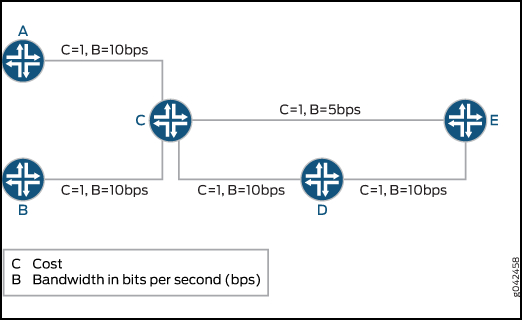
Here’s a pic I stole from Juniper’s website. Technically this is a crime. Please don’t tell the FBI.
Notice how all the links are 10Mb, apart from the link between C and E, which is 5Mb.
Now imagine two LSPs:
- One called A_to_E, which needs 10Mb bandwidth
- One called B_to_E, which only needs 5Mb
What happens if the B_to_E LSP comes up first? Our router will correctly decide that the B–>C–>D–>E path is metrically best, so it will create the LSP down that path, with a 5Mb bandwidth reservation.
A few moments later the A_to_E LSP tries to come up. This LSP needs 10Mb. Do you see the problem? There is a 10Mb path that it could have all to itself. Sadly though, B_to_E got in there first. As such, there is no single path that has a full 10Mb available. And all because B_to_E came up first!
If we used priorities then we could solve this, because then A_to_E could kick B_to_E off. But in reality, chances are that these LSPs are of equal priority.
Perhaps we could use something like Northstar, or some other vendor LSP controller, to manage the network? This would definitely work: one single controller can move LSPs in order to make way for other LSPs. Controllers help with the bin-packing problem by having a truly full view of the network. But of course, this involves having that software in the first place!
How do Container LSPs fix this? By splitting the 10Mb LSP into two 5Mb LSPs, the bin packing problem is far less likely to bring our network to a stand-still: our 10Mb LSP can indeed be split into two 5Mb LSPs, and each one can take a different path to the destination.
LET’S LOOK AT OUR LAB NETWORK TODAY
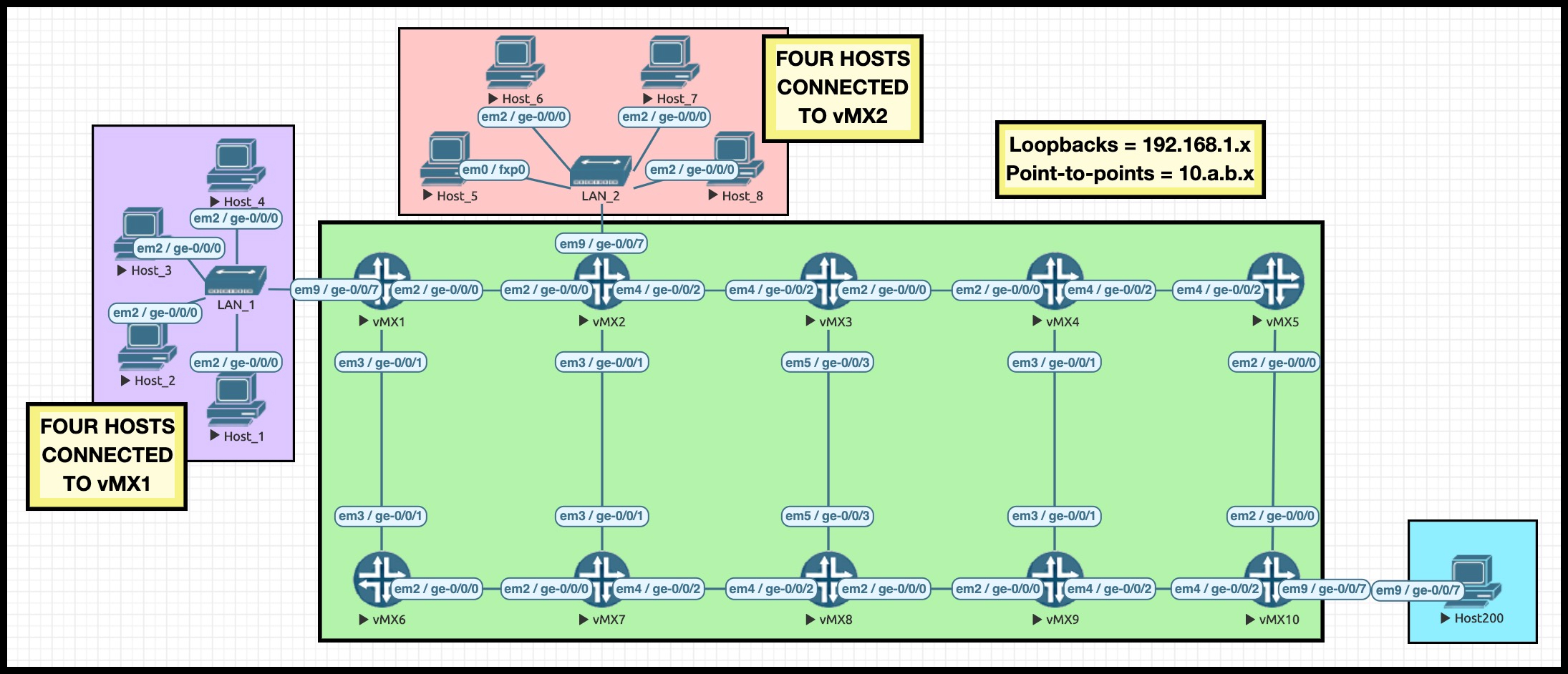
Hey there: it’s the return of my famous Ten Router Lab! What makes it famous, you ask? Good question: my Ten Router Lab has just been signed up to be the next James Bond. Please look forward to seeing my famous Ten Router Lab on the silver screen next year, in “James Bond: License To Route”.
Y’already know what it is: The IPs are numbered to easily show us which routers connect to which. As an example, 10.2.7.2/24 is Router 2’s interface on the link between Routers 2 and 7. The interface on Router 7 would be 10.2.7.7/24. As for loopbacks, Router 10’s loopback is 192.168.1.10. If you understand that, then you’ll easily be able to read the Explicit Route Objects in our LSPs, to see what path they’re taking.
Take a moment to look at the ten routers in the core, and where they are in the topology. In fact, I highly recommend opening the topology in a separate tab, so you can easily refer back to it as you read this post. I even made the pic a clickable link for you. Wow, what a nice guy I am!
Today we have two goals. The first is to make a Container LSP. The second is to find true love. Let’s talk a bit about the first goal, and hope that destiny takes care of the second.
WHAT ARE WE GONNA ACHIEVE TODAY?
We’re going to make a Container LSP called R1_TO_R10. Looking at the topology, can you guess which router it’s going from and going to?
It might look like all these links are all equal-cost, but actually I’ve manipulated the metrics so that the shortest path from R1 to R10 is R1–>R2–>R3–>R4–>R5–>R10. From now on I’ll refer to this simply as the “top path”. Knowing this will help us to easily spot when things change, and an LSP takes the less good “bottom path” (R1–>R6–>R7–>R8–>R9–>R10).
You’ll see that there are some hosts connected to R1. A single large rapid ping stream from one of these hosts creates around 1.3Mb of traffic. With that in mind, here’s what I’m going to do:
- Create a Container LSP that can have a maximum of 5 LSPs and a minimum of 1 LSP
- Trigger the creation of new member LSPs if the bandwidth over the Container goes over a multiple of 2Mb
- Trigger the tearing down (aka the merging) of member LSPs if aggregate bandwidth goes under a multiple of 1.5Mb
And one final thing: I’m going to trick RSVP into thinking that all of the links in my network are just 5Mb. Why? As we start new pings on the hosts, we’ll see that the Container creates new members – but that initially all the Member LSPs take the same top path, because there’s enough bandwidth available for all of them. By setting the bandwidth on each interface in the network to just 5Mb, it won’t be too long before I’m able to show you what it looks like when a link “maxes out”, and auto-bandwidth kicks in. Naughty naughty, very naughty!
root@vMX_1> show rsvp interface
RSVP interface: 4 active
                          Active  Subscr- Static      Available   Reserved    Highwater
Interface          State  resv    iption  BW          BW          BW          mark
ge-0/0/0.0             Up       0   100%  5Mbps       5Mbps       0bps        0bps
ge-0/0/1.0             Up       0   100%  5Mbps       5Mbps       0bps        0bps
ge-0/0/7.0             Up       0   100%  5Mbps       5Mbps       0bps        0bps
lo0.0                  Up       0   100%  5Mbps       5Mbps       0bps        0bps
BRINGING UP THE CONTAINER LSP
So, our MPLS statistics config from Part 2 is already on the box.
I’ve just added the example template and container LSP config that I showed you earlier in this post. Remember, we set our container to split at 2Mb, merge at 1.5Mb, and normalize every 600 seconds.
How do we view the results of our config? You’ll already be familiar with the “show mpls lsp” command. So you’ll be delighted to know that the equivalent command for container LSPs is simply “show mpls container-lsp“!
Although confusingly, this command actually shows you not just your container LSP and member LSPs, but also any other regular LSPs that start/end on this box as well. So in other words, it shows you everything. The folks at Junos code HQ were smoking the good stuff when they decided what this command does, I tell you.
I’ve used the “ingress” option in my command to focus in on the LSP I just made:
root@vMX_1> show mpls container-lsp ingress
Ingress LSP: 1 sessions
Container LSP name                              State     Member LSP count
R1_TO_R10_CONTAINER                             Up                1
To              From            State Rt P     ActivePath       LSPname
192.168.1.10    192.168.1.1     Up     0 *                      R1_TO_R10_CONTAINER-1
Total 1 displayed, Up 1, Down 0
Looking good! We see our container LSP, and we also see a single member LSP, called “R1_TO_R10_CONTAINER-1”. If you use your imagination to its fullest, you can probably predict what the second and third member LSPs might get automatically named!
Okay, so the container LSP exists. Let’s crack it open and look at the details.
DIVING DEEP INTO THE EXTENSIVE OUTPUT
Notice that the output below is actually split into two: the top half is all about the Container LSP, and then the bottom half is info about our single Member LSP.
There’s a lot going on in the output below, so as you read it, here’s some things to look out for:
- We see that this is indeed a container LSP, and we see all the stats that we configured on it: there’ll always be at least one LSP up, and at most 5.
- We see the splitting and merging bandwidth we configured too.
- And we can see that the countdown to normalization has begun: it’s 555 seconds away from normalization.
- It’s interesting that it says there’s an aggregate bandwidth of 1.5Mb, because there’s currently no traffic going over this network at all. I only highlight this because later on, as traffic does indeed go over the network, we’ll see this number changes to represent the truth.
- The second half of the output will already be familiar to you from our lesson on Auto-Bandwidth: we see the LSP name, the bandwidth reservation, the priority, the auto-bandwidth countdown, all that good stuff.
- We also see from the Explicit Route Object that this member LSP is indeed taking the top path in our network, just like we wanted it to.
root@vMX_1> show mpls container-lsp ingress extensive
Ingress LSP: 1 sessions
Container LSP name: R1_TO_R10_CONTAINER, State: Up, Member count: 1
 Normalization
  Min LSPs: 1, Max LSPs: 5
  Aggregate bandwidth: 1.5Mbps, Sampled Aggregate bandwidth: 0bps
  NormalizeTimer: 600 secs, NormalizeThreshold: 10%
  Max Signaling BW: 2Mbps, Min Signaling BW: 1.5Mbps, Splitting BW: 2Mbps, Merging BW: 1.5Mbps
  Mode: incremental-normalization, no-failover-normalization
  Sampling: Outlier cut-off 0, Max Aggregate
  Normalization in 555 second(s)
    4 Feb  1 20:34:35.272 Normalization complete: container (R1_TO_R10_CONTAINER) with 1 members
    3 Feb  1 20:34:05.616 Normalize: container (R1_TO_R10_CONTAINER) into 1 members - each with bandwidth 1500000 bps
    2 Feb  1 20:34:05.616 Normalize: container (R1_TO_R10_CONTAINER) create 1 LSPs, min bw 1500000bps, member count 0
    1 Feb  1 20:34:05.616 Normalize: normalization with aggregate bandwidth 0 bps

192.168.1.10
  From: 192.168.1.1, State: Up, ActiveRoute: 0, LSPname: R1_TO_R10_CONTAINER-1
  ActivePath:  (primary)
  LSPtype: Dynamic Configured, Penultimate hop popping
  LoadBalance: Random
  Autobandwidth
  MinBW: 1000bps, MaxBW: 100Gbps
  AdjustTimer: 300 secs AdjustThreshold: 5%
  Max AvgBW util: 0bps, Bandwidth Adjustment in 255 second(s).
  Overflow limit: 0, Overflow sample count: 0
  Underflow limit: 0, Underflow sample count: 0, Underflow Max AvgBW: 0bps
  Encoding type: Packet, Switching type: Packet, GPID: IPv4
  LSP Self-ping Status : Enabled
 *Primary                    State: Up
    Priorities: 5 5
    Bandwidth: 1.5Mbps
    SmartOptimizeTimer: 180
    Flap Count: 0
    MBB Count: 0
    Computed ERO (S [L] denotes strict [loose] hops): (CSPF metric: 50)
 10.1.2.2 S 10.2.3.3 S 10.3.4.4 S 10.4.5.5 S 10.5.10.10 S
Another interesting thing: notice that this is a “Dynamically configured” LSP. Normally when you create an LSP it says that it’s static, because you made it manually. Kind of an interesting thing! Kind of interesting, right? Kind of interesting.
Remember that this member LSP is, to all intents and purposes, just a regular LSP. You could do a “show mpls lsp name R1_TO_R10_CONTAINER-1” on any router in the path, to see the info specifically about this member LSP.
By the way: now you’ve seen the full output of this command, for the rest of this blog post I’m going to very heavily edit the rest of the examples, and delete any lines that aren’t relevant. This literally reduces the size of this blog post by half, and it definitely makes things easier to read!
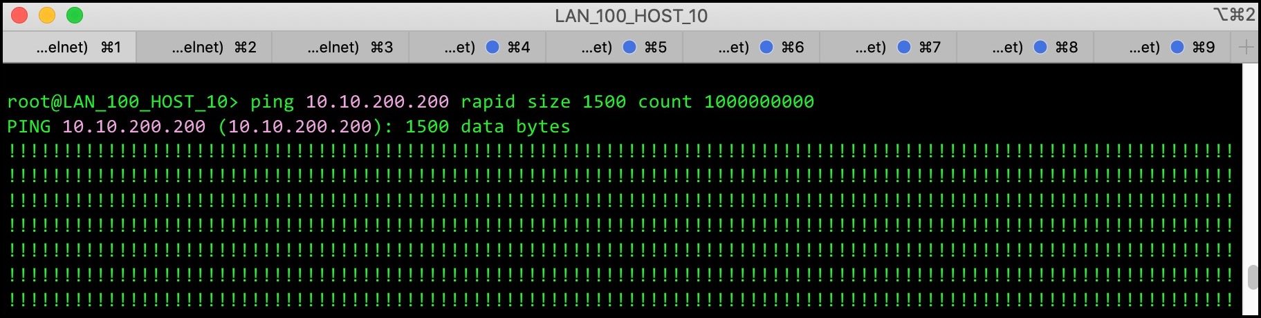
Right, let’s shake things up. Let’s hop onto Host 1 and generate some traffic.
GENERATING TRAFFIC DOWN OUR MEMBER LSP
Here’s what the CLI looks like on Host 1: rapid pings for days, all 1500 size. I can’t be bothered to count how many zeros I put in the “count”, but at a guess I’d say it was approximately a quadra-squillion.
I wait 5 minutes (aka 300 seconds), as per the auto-bandwidth config in our template, and then I check back in on the Member LSP. At this stage the normalization timer is still counting down, so rather than looking at the full container, for now let’s type a command that just looks at the individual member LSP.
Remember, I’m deleting lots of the output so we can focus in on what matters:
root@vMX_1> show mpls lsp name R1_TO_R10_CONTAINER-1 detail
Ingress LSP: 1 sessions

192.168.1.10
  From: 192.168.1.1, State: Up, ActiveRoute: 0, LSPname: R1_TO_R10_CONTAINER-1
 *Primary                    State: Up
    Priorities: 5 5
    Bandwidth: 1.34738Mbps
    Computed ERO (S [L] denotes strict [loose] hops): (CSPF metric: 50)
 10.1.2.2 S 10.2.3.3 S 10.3.4.4 S 10.4.5.5 S 10.5.10.10 S
Told you it was way easier to read when I deleted tons of the output, right?
Above we can see that the LSP re-signalled its bandwidth (and it did this because 1.347Mb is 5% smaller than 1.5Mb). This highlights the fact that each Member LSP has its own auto-bandwidth timer which it inherits from the template. It also highlights that this is separate from the normalization timer that checks if new Member LSPs need to be created, or old ones torn down.
So what happens when the normalization timer reaches zero? In this case, nothing. The total bandwidth is not over 2Mb, so there’s no need for a new Member. LSP. We actually see this in the container logs:
root@vMX_1> show mpls container-lsp ingress extensive
Ingress LSP: 1 sessions
Container LSP name: R1_TO_R10_CONTAINER, State: Up, Member count: 1
  Normalization in 592 second(s)
    7 Feb  1 20:44:06.628 Clear history and statistics: on container (R1_TO_R10_CONTAINER)
    6 Feb  1 20:44:05.617 Avoid normalization: not needed with bandwidth 1347379 bps
    5 Feb  1 20:44:05.617 Avoid normalization: Has minimum number of lsps with reserved minimum-bandwidth
    4 Feb  1 20:34:35.272 Normalization complete: container (R1_TO_R10_CONTAINER) with 1 members
At this stage I’d like to show you the reserved bandwidth on each interface on Router 1. Later on in this post you’ll see why I’m showing you this now, because in a moment we’re going to see something very surprising.
As you’d expect, the interface facing R2 is the only one with any bandwidth reserved, and we see that it’s reserving 1.34738Mbps, which is exactly how much our Member LSP requested above.
root@vMX_1> show rsvp interface
RSVP interface: 4 active
                          Active  Subscr- Static      Available   Reserved    Highwater
Interface          State  resv    iption  BW          BW          BW          mark
ge-0/0/0.0             Up       1   100%  5Mbps       3.65262Mbps 1.34738Mbps 1.5Mbps
ge-0/0/1.0             Up       0   100%  5Mbps       5Mbps       0bps        0bps
ge-0/0/7.0             Up       0   100%  5Mbps       5Mbps       0bps        0bps
lo0.0                  Up       0   100%  5Mbps       5Mbps       0bps        0bps
Our rapid large pings on Host 1 are still going. Let’s get funky, and get the same thing going on Host 2. With any luck, this will take us over the 2Mb splitting limit, and we’ll see some good stuff!
SPLITTING OUR MEMBER LSP INTO TWO
Two rapid pings are currently happening, and the normalization timer is counting down.
While we wait, we can actually check to see what the average bandwidth currently is within the larger container (although at the moment the “larger container” is just one single member LSP). In the output below we see it’s currently 2.49414Mbps, and that the normalization will happen in 277 seconds. Remember, from now on I’m deleting irrelevant lines in the output, so in your lab you’ll see much more output than this!
root@vMX_1> show mpls container-lsp ingress extensive
Ingress LSP: 1 sessions
Container LSP name: R1_TO_R10_CONTAINER, State: Up, Member count: 1
 Normalization
  Min LSPs: 1, Max LSPs: 5
  Aggregate bandwidth: 2.49414Mbps, Sampled Aggregate bandwidth: 2.49414Mbps
  Normalization in 277 second(s)
So, I wait 277 seconds. I make a cup of tea, I read a book, I bury some treasure, I alphabetise my socks, and then, when I come back, we see in the output below: two LSPs!
Here’s a list of things to look out for as you read the output below:
- In the container LSP section, the Member Count is now 2
- We see in the container logs that the aggregate bandwidth was enough to trigger the creation of a second member LSP.
- We also see in the container logs that the decision has been made to signal each member LSP with 1.5Mb bandwidth.
- We then see our two individual members: R1_TO_R10_CONTAINER-1, and R1_TO_R10_CONTAINER-2, both reserving 1.5Mb bandwidth.
- Interestingly, we see that the original R1_TO_R10_CONTAINER-1 LSP has been “normalized” to 1.5Mb, which actually makes sense when you think that suddenly a lot of the traffic this LSP was previously carrying has now been moved to a new LSP. As such, the previous bandwidth probably isn’t accurate any more, so it’s easier to just split the difference, and start over in terms of the bandwidth that each member reserves
- Each member LSP also takes the top path, which makes sense because there is currently enough bandwidth on that path for both of these members. There’s no need for them to take diverse paths. Of course, if this were to change in the future then auto-bandwidth would have the flexibility to create some path diversity.
root@vMX_1> show mpls container-lsp ingress extensive
Ingress LSP: 1 sessions
Container LSP name: R1_TO_R10_CONTAINER, State: Up, Member count: 2
 Normalization
  Min LSPs: 1, Max LSPs: 5
  Aggregate bandwidth: 3Mbps, Sampled Aggregate bandwidth: 0bps
  Normalization in 587 second(s)
   11 Feb  1 20:54:06.638 Clear history and statistics: on container (R1_TO_R10_CONTAINER)
   10 Feb  1 20:54:06.225 Normalization complete: container (R1_TO_R10_CONTAINER) with 2 members
    9 Feb  1 20:54:05.617 Normalize: container (R1_TO_R10_CONTAINER) into 2 members - each with bandwidth 1500000 bps
    8 Feb  1 20:54:05.617 Normalize: normalization with aggregate bandwidth 2494137 bps

192.168.1.10
  From: 192.168.1.1, State: Up, ActiveRoute: 0, LSPname: R1_TO_R10_CONTAINER-1
 *Primary                    State: Up
    Priorities: 5 5
    Bandwidth: 1.5Mbps
    Computed ERO (S [L] denotes strict [loose] hops): (CSPF metric: 50)
 10.1.2.2 S 10.2.3.3 S 10.3.4.4 S 10.4.5.5 S 10.5.10.10 S

192.168.1.10
  From: 192.168.1.1, State: Up, ActiveRoute: 0, LSPname: R1_TO_R10_CONTAINER-2
 *Primary                    State: Up
    Priorities: 5 5
    Bandwidth: 1.5Mbps
    Computed ERO (S [L] denotes strict [loose] hops): (CSPF metric: 50)
 10.1.2.2 S 10.2.3.3 S 10.3.4.4 S 10.4.5.5 S 10.5.10.10 S
A QUICK NOTE ON WHAT “SPLITTING” REALLY MEANS
At this point it’s worth pointing out an interesting thing about auto-bandwidth.
We talk about an LSP re-signalling its bandwidth requirements, but strictly speaking that isn’t quite true.
In actual fact, a second LSP with the same name is created. One of them will have the old bandwidth requirement, and one of them will have the new bandwidth requirement. Luckily they’re signalled with the “shared explicit” reservation style, which means that the bandwidth requirements of these two separate LSPs isn’t double-counted on the link. Instead, the largest number is used for both of them. This fact will be important later on.
root@vMX_1> show rsvp session ingress
Ingress RSVP: 3 sessions
To              From            State   Rt Style Labelin Labelout LSPname
192.168.1.10    192.168.1.1     Up       0  1 SE       -   301408 R1_TO_R10_CONTAINER-1
192.168.1.10    192.168.1.1     Up       0  1 SE       -   301440 R1_TO_R10_CONTAINER-1
192.168.1.10    192.168.1.1     Up       0  1 SE       -   301424 R1_TO_R10_CONTAINER-2
Total 3 displayed, Up 3, Down 0
Notice above that the “Labelout” is different on each LSP, which shows that they are different even though they have the same name.
Once the “new” LSP is created and is shown to be stable, traffic is moved over to the “new” LSP, and then the “old” LSP is torn down. This all happens gracefully, make-before-break.
Sadly the “extensive” version of that command doesn’t show you every single element of the RSVP message, but you can see below that both of these LSPs with the same name actually have the same tunnel ID, shown here as the “port number”. (Once again, this output is heavily edited for size.)
root@vMX_1> show rsvp session extensive
Ingress RSVP: 3 sessions

192.168.1.10
  From: 192.168.1.1, LSPstate: Up, ActiveRoute: 0
  LSPname: R1_TO_R10_CONTAINER-1, LSPpath: Primary
  Resv style: 1 SE, Label in: -, Label out: 301408
  Tspec: rate 2.49414Mbps size 2.49414Mbps peak Infbps m 20 M 1500
  Port number: sender 3 receiver 49846 protocol 0

192.168.1.10
  From: 192.168.1.1, LSPstate: Up, ActiveRoute: 0
  LSPname: R1_TO_R10_CONTAINER-1, LSPpath: Primary
  Resv style: 1 SE, Label in: -, Label out: 301440
  Tspec: rate 1.5Mbps size 1.5Mbps peak Infbps m 20 M 1500
  Port number: sender 4 receiver 49846 protocol 0
If you do a packet capture on the RSVP messages, you’ll see that this LSP has a tunnel ID of 0xc2b6, which is hex for 49846. Bit of a roundabout way for the router to show us that info, but there we are!

If we check RSVP on the interfaces, we can confirm that the bandwidth isn’t being double-counted. In the output below you’ll see the following::
- The interface facing R2 currently has 3.99414Mbps reserved.
- That’s 1.5Mb for our new R1_TO_R10_CONTAINER-2
- Plus whichever bandwidth is higher from the two R1_TO_R10_CONTAINER-1 LSPs, which in this case happens to be 2.49414Mbps.
2.49414Mb + 1.5Mb = 3.9914Mb. Maths is fun!
root@vMX_1> show rsvp interface
RSVP interface: 4 active
                          Active  Subscr- Static      Available   Reserved    Highwater
Interface          State  resv    iption  BW          BW          BW          mark
ge-0/0/0.0             Up       2   100%  5Mbps       1.00586Mbps 3.99414Mbps 3.99414Mbps
ge-0/0/1.0             Up       0   100%  5Mbps       5Mbps       0bps        0bps
ge-0/0/7.0             Up       0   100%  5Mbps       5Mbps       0bps        0bps
lo0.0                  Up       0   100%  5Mbps       5Mbps       0bps        0bps
FORCING THE CONTAINER TO CREATE A THIRD MEMBER – AND DISCOVERING SOMETHING UNEXPECTED
So, we’ve got two member LSPs, and two constant pings going. I leave the traffic flowing for a while, and soon enough auto-bandwidth re-signals each LSP with the new bandwidth requirements.
After the normalization timer counts down to zero, nothing happens. After all, the bandwidth isn’t big enough to trigger a change.
I get a third ping going. After a while, I check in:
root@vMX_1> show mpls container-lsp ingress extensive
Ingress LSP: 1 sessions
Container LSP name: R1_TO_R10_CONTAINER, State: Up, Member count: 2
 Normalization
  Min LSPs: 1, Max LSPs: 5
  Aggregate bandwidth: 3.51128Mbps, Sampled Aggregate bandwidth: 3.51128Mbps
Not quite enough to trigger the creation of a third member. So, I get a fourth ping going. After a short while I check back in, and I see the aggregate bandwidth is now 4.2Mb. Excellent!
When the normalization counter hits zero, three Member LSPs will exist, each with 1.5Mb bandwidth”. That’s 4.5Mb bandwidth in total.
Now, remember in my lab I’ve got 5Mb RSVP interfaces everywhere. With that in mind, when I was new to container LSPs what I assumed would happen at this point is that the three member LSPs would come up, and all three LSPs would go down the top, “best”, path.
And yet, if you’re playing along at home, if you check your “show rsvp interface” when the three member LSPs come up then you’ll see bandwidth reservations that are wildly different – and now only that, you’ll also see one of the members taking the bottom path in my network!
Why on earth did this happen? Let me explain.
As expected, a third member is created. In addition, the two existing members also “re-signal” their bandwidth, which as we’ve seen really means we’re creating new LSPs with the same name. Check it out below:
root@vMX_1> show rsvp session
Ingress RSVP: 5 sessions
To              From            State   Rt Style Labelin Labelout LSPname
192.168.1.10    192.168.1.1     Up       0  1 SE       -   301536 R1_TO_R10_CONTAINER-1
192.168.1.10    192.168.1.1     Up       0  1 SE       -   301568 R1_TO_R10_CONTAINER-1
192.168.1.10    192.168.1.1     Up       0  1 SE       -   301552 R1_TO_R10_CONTAINER-2
192.168.1.10    192.168.1.1     Up       0  1 SE       -   301584 R1_TO_R10_CONTAINER-2
192.168.1.10    192.168.1.1     Up       0  1 SE       -   300544 R1_TO_R10_CONTAINER-3
Total 5 displayed, Up 5, Down 0
The output of our “show mpls container-lsp” command below confirms the fact that we created enough bandwidth to trigger a third member – and that each member should be re-signalled with 1.5Mb. I’ve marked it in red below. in the container logs
root@vMX_1> show mpls container-lsp ingress extensive
Ingress LSP: 1 sessions
Container LSP name: R1_TO_R10_CONTAINER, State: Up, Member count: 3
 Normalization
  Min LSPs: 1, Max LSPs: 5
  Aggregate bandwidth: 4.5Mbps, Sampled Aggregate bandwidth: 0bps
  Normalization in 590 second(s)
   22 Feb  1 21:24:06.648 Clear history and statistics: on container (R1_TO_R10_CONTAINER)
   21 Feb  1 21:24:06.602 Normalization complete: container (R1_TO_R10_CONTAINER) with 3 members
   20 Feb  1 21:24:05.620 Normalize: container (R1_TO_R10_CONTAINER) into 3 members - each with bandwidth 1500000 bps
   19 Feb  1 21:24:05.620 Normalize: normalization with aggregate bandwidth 4357930 bps
The output of the “show mpls container-lsp” command continues below, with our three member LSPs.
All three LSPs are clearly reporting that they’re using 1.5Mb bandwidth. And yet, at the bottom there we see quite clearly that R1_TO_R10_CONTAINER-3 is taking the bottom path. There’s more than enough bandwidth in the network. So why is this happening?
As always, I’ve heavily edited the CLI output:
192.168.1.10
  From: 192.168.1.1, State: Up, ActiveRoute: 0, LSPname: R1_TO_R10_CONTAINER-1
 *Primary                    State: Up
    Priorities: 5 5
    Bandwidth: 1.5Mbps
    Computed ERO (S [L] denotes strict [loose] hops): (CSPF metric: 50)
 10.1.2.2 S 10.2.3.3 S 10.3.4.4 S 10.4.5.5 S 10.5.10.10 S

192.168.1.10
  From: 192.168.1.1, State: Up, ActiveRoute: 0, LSPname: R1_TO_R10_CONTAINER-2
 *Primary                    State: Up
    Priorities: 5 5
    Bandwidth: 1.5Mbps
    Computed ERO (S [L] denotes strict [loose] hops): (CSPF metric: 50)
 10.1.2.2 S 10.2.3.3 S 10.3.4.4 S 10.4.5.5 S 10.5.10.10 S

192.168.1.10
  From: 192.168.1.1, State: Up, ActiveRoute: 0, LSPname: R1_TO_R10_CONTAINER-3
 *Primary                    State: Up
    Priorities: 5 5
    Bandwidth: 1.5Mbps
    Computed ERO (S [L] denotes strict [loose] hops): (CSPF metric: 60)
 10.1.6.6 S 10.6.7.7 S 10.7.8.8 S 10.8.9.9 S 10.9.10.10 S
EXPLAINING THE UNEXPECTED
Earlier on, we saw that the “show mpls lsp” command doesn’t show you as much as “show rsvp session“.
If an auto-bandwidth LSP is “re-signalling” – ie creating a second LSP with the same name and the same tunnel ID, moving traffic over to the new LSP, and then tearing the first LSP down – then the “show mpls lsp” command actually hides this from us. We only see the two “duplicate” LSPs when we type “show rsvp session“.
In a way this makes sense: conceptually they’re the same MPLS LSP, with two separate RSVP sessions.
Now, if you didn’t know about this quirk of auto-bandiwdth, then the fact that R1_TO_R10_CONTAINER-3 is going a different way would confuse the heck out of you. After all, the output above couldn’t be clearer: each LSP is now signalling 1.5Mb bandwidth. And you’d be especially confused when you look at the RSVP interfaces, and see way more than 4.5Mb bandwidth reserved in total:
root@vMX_1> show rsvp interface
RSVP interface: 4 active
                          Active  Subscr- Static      Available   Reserved    Highwater
Interface          State  resv    iption  BW          BW          BW          mark
ge-0/0/0.0             Up       2   100%  5Mbps       629.068kbps 4.37093Mbps 4.37093Mbps
ge-0/0/1.0             Up       1   100%  5Mbps       3.5Mbps     1.5Mbps     1.5Mbps
ge-0/0/7.0             Up       0   100%  5Mbps       5Mbps       0bps        0bps
lo0.0                  Up       0   100%  5Mbps       5Mbps       0bps        0bps
Clearly our new member LSP, R1_TO_R10_CONTAINER-3 LSP, is going out of ge-0/0/1.0, which is the interface to Router 6. We can see that it’s reserving the 1.5Mb correctly.
Now according to our “show mpls container-lsp” command, R1_TO_R10_CONTAINER-1 and R1_TO_R10_CONTAINER-2 are also only requesting 1.5Mb of bandwidth. And yet, on ge-0/0/0.0 (the interface facing R2), we see above that theres over 4.3Mb bandwidth reserved! How?
Perhaps it’s starting to make sense now why I took a slight diversion earlier to show you how the duplicate LSPs are signalled. It’s true that the bandwidth between the duplicate LSPs isn’t double-counted – but it’s also true that the biggest bandwidth wins. And of course, the previous versions of R1_TO_R10_CONTAINER-1 and R1_TO_R10_CONTAINER-2 were signalling more than 1.5Mb of bandwidth. That’s why the number is higher than 1.5Mb.
If we do a “show rsvp session extensive“, we can see this in action. Again, the output below is heavily edited:
root@vMX_1> show rsvp session extensive
Ingress RSVP: 5 sessions

192.168.1.10
  LSPname: R1_TO_R10_CONTAINER-1, LSPpath: Primary
  Tspec: rate 2.23531Mbps size 2.23531Mbps peak Infbps m 20 M 1500
  Port number: sender 8 receiver 49846 protocol 0
  Explct route: 10.1.2.2 10.2.3.3 10.3.4.4 10.4.5.5 10.5.10.10

192.168.1.10
  LSPname: R1_TO_R10_CONTAINER-1, LSPpath: Primary
  Tspec: rate 1.5Mbps size 1.5Mbps peak Infbps m 20 M 1500
  Port number: sender 9 receiver 49846 protocol 0
  Explct route: 10.1.2.2 10.2.3.3 10.3.4.4 10.4.5.5 10.5.10.10

192.168.1.10
  LSPname: R1_TO_R10_CONTAINER-2, LSPpath: Primary
  Tspec: rate 2.13562Mbps size 2.13562Mbps peak Infbps m 20 M 1500
  Port number: sender 4 receiver 49847 protocol 0
  Explct route: 10.1.2.2 10.2.3.3 10.3.4.4 10.4.5.5 10.5.10.10

192.168.1.10
  LSPname: R1_TO_R10_CONTAINER-2, LSPpath: Primary
  Tspec: rate 1.5Mbps size 1.5Mbps peak Infbps m 20 M 1500
  Port number: sender 5 receiver 49847 protocol 0
  Explct route: 10.1.2.2 10.2.3.3 10.3.4.4 10.4.5.5 10.5.10.10

192.168.1.10
  LSPname: R1_TO_R10_CONTAINER-3, LSPpath: Primary
  Tspec: rate 1.5Mbps size 1.5Mbps peak Infbps m 20 M 1500
  Port number: sender 1 receiver 49848 protocol 0
  Explct route: 10.1.6.6 10.6.7.7 10.7.8.8 10.8.9.9 10.9.10.10
The two “existing” LSPs had a bandwidth of 2.23531Mbps and 2.13562Mbps respectively. My friendly neighbourhood calculator tells me that those two numbers added together equals 4.37093Mbps. And, as chance would have it, that’s exactly how much is reserved on the interface facing R2!
For this reason, don’t be concerned if new member LSPs initially take a sub-optimal path. Once the next auto-bandwidth period hits they’ll run CSPF again, by which point those old LSPs will be long-gone, and your new Member LSP will indeed be able to calculate the best path again.
When I first discovered this, it confused me so much. Either this isn’t mentioned in the documentation, or is mentioned and I’m just too dumb to see it. In any case, I hope this explanation helps you to understand why this is happening.
So there you have it: that’s the basics of Container LSPs! Have a play, and see if you like them!
ONE FINAL THING TO REMEMBER
On Juniper boxes (and on most vendors, I think), load balancing doesn’t happen per-packet, but instead happens per-flow. This is a good thing: it means that a single source/destination/application tuple will always take the same path, and therefore won’t be prone to the kind of problems that could occur if half of the session took a physically different path to the other half of the session. Packets could arrive out of order, and the jitter could be unbearable for real-time applications.
Equal-cost multipath isn’t turned on by default. You have to enable it. And the command to do this is quite possibly the stupidest command that any vendor has ever made. You create a policy, and you apply it to the forwarding-table. The policy is one single line of config, with no “from” statement, meaning it matches everything. And that single line…. looks like this:
set policy-options policy-statement LOAD_BALANCE then load-balance per-packet
set routing-options forwarding-table export LOAD_BALANCE
Yes, you read that right: “load-balance per-packet” ACTUALLY enables per-flow load balancing. The reasons for this are historical and tedious, and the result is one of the most confusing and misunderstood commands in all of Junos. It’s truly maddening, and believe me when I say that I’m slowly, slowly trying to convince people to get this changed.
But that’s a topic for another day. Without this command, your router can’t do per-flow load-balancing. It will create multiple member LSPs, but it will carry on just sending traffic down only one of the member LSPs. You’ll see it in the “show mpls container-lsp” output: you’ll probably have three LSPs signalling the minimum bandwidth (1k from our template), and the one single LSP signalling something like 4.5Mb all to itself.
So be sure to add this essential config on if you plan to use Container LSPs!
THAT’S IT!
Thank you so much as always for reading my post. Do you use Container LSPs? If you have any stories of success, or indeed of failure, please do share them in the comments.
If you enjoyed this post, there’s a few ways to support me. Donations are always welcome so I can break even on my lab, and on the hosting on this website. If you share this post on your favourite social media of choice then you’ll be helping me to get through to even more readers. And while you’re here, why not head to the homepage of my website to flick through all my older posts. Maybe there’s other stuff you’ll enjoy!
If you’re on Mastodon, follow me to find out when I make new posts. (2024 edit: I’m also on BlueSky nowadays too. I was once on Twitter, but I’ve given up on it, on account of… well, I don’t need to finish that sentence, do I.)
And hey: if you didn’t enjoy this post, why not write to the United Nations to complain? Perhaps António Guterres will personally see to it that I’m brought to justice for making posts that you didn’t enjoy. Worth a go, if you ask me.


Great explanation! Thanks for sharing.