

Your “Multihop” BGP Session Probably Isn’t Multi-Hop
The inventors of the IP header missed a trick when they named the hop count field the “time to live”. They should, of course, have called it the “time to die” field. What a wasted opportunity for mayhem and hijinks.
While we’re on the topic, I also think they should have forced everyone to write it in caps lock, with a menacing laugh after it. The fact that they never did this is a damning indictment of the IETF’s priorities. As always, the burden falls on me to solve everyone’s problems. I have proposed RFC 69420, which renames the TTL field to the “TIME TO DIE!!! MWA HA HA HA HA!!!” field.
I expect fierce resistance to this proposal, on account of the fact that every single person in the network engineering industry apart from me is a coward. Nevertheless, I will fight this battle to my very death. Or, to the end of the day. Whichever one comes first. (Obviously I hope death comes first, but beggars can’t be choosers.)
Anyway, can you please just shut up for once and stop distracting me? I’m trying to welcome you to this blog post about BGP.
Today we’re going to look at External BGP (EBGP) peerings that operate between the loopback IPs of two directly connected routers.
You might already know that by default, such a peering will not work, because EBGP packets are sent with a TTL of 1. To fix this, you have to configure something called “multihop”, which sets the TTL to be something larger than 1.
Unfortunately, this fact leads many new students to make some incorrect conclusions about the way that the TTL value is processed.
Upon learning about EBGP and multihop, many new students assume that a directly connected router will decrement the TTL before accepting a packet on a loopback interface. In fact though, this is not the case. The TTL can definitely be 1, and it will work absolutely fine.
In today’s post we’re going to unpick the confusion, and take a close look at how the TTL really works—and how it can actually be used to increase the security in your network, using something called the Generalized TTL Security Mechanism.
First though, let’s get ourselves clear on when the TTL is actually decremented.
WHEN IS THE TTL DECREMENTED?
The time-to-live field is a number in the IPv4 header that goes down by one every time a packet passes through some kind of “layer 3 device”—in other words, a device that connects two or more subnets together, and can forward packets between them. Whether it’s a router, a firewall, a “layer 3 switch”, or even the special cables you run through your granddad at Christmas, the point is that the TTL is decremented by 1 when:
- A packet enters a device;
- A layer 3 lookup happens;
- The packet is forwarded to a new subnet;
- The packet either exits the physical device, or is forwarded to a different virtual instance (eg a VRF, a virtual router, etc) within the device.
The equivalent field in the IPv6 header is the “hop count” field. Much more meaningful name, in my opinion.
You probably know already that the purpose of this TTL/hop count field is to prevent catastrophic problems when a routing loop occurs. Thanks to the TTL, packets will eventually be dropped when this value reaches zero. Even if a packet loops a few dozen times around a network, it will eventually be discarded.
Here’s a crucial point to understand: if a packet arrives at its destination, the TTL is not decremented one final time. In other words, suppose you SSH to a router. Let’s say the SSH packet arrives at the router with a TTL of 60. In this case, the router simply processes the SSH information. It does not set the TTL value to 59, and then process the payload.
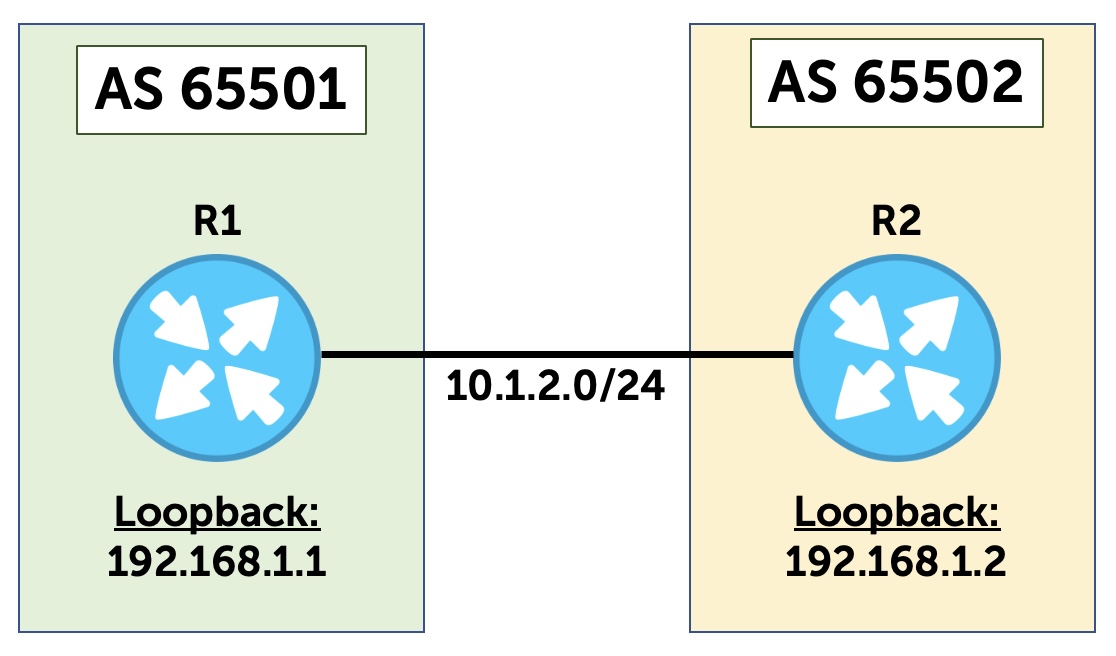
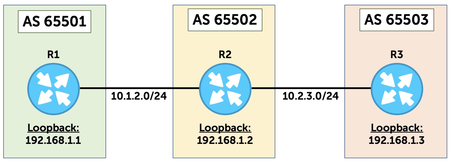
This is true even if you SSH to a different IP than the one on the incoming interface. You know: like SSHing to the loopback IP of a device. In fact, let’s test this. This diagram shows the topology we’re going to use for most of this post. Two routers, each at the border of an autonomous system. R1’s interface on this shared link is 10.1.2.1, and R2’s interface is 10.1.2.2.
Let’s go onto R1, and ping R2’s loopback – with a TTL of 1:
root@R1> ping 192.168.1.2 ttl 1
PING 192.168.1.2 (192.168.1.2): 56 data bytes
64 bytes from 192.168.1.2: icmp_seq=0 ttl=64 time=3.823 ms
64 bytes from 192.168.1.2: icmp_seq=1 ttl=64 time=2.633 ms
^C
--- 192.168.1.2 ping statistics ---
2 packets transmitted, 2 packets received, 0% packet loss
round-trip min/avg/max/stddev = 2.633/3.228/3.823/0.595 ms
Voila – we have success! If the ping were decremented by one as soon as the packet arrived on the incoming interface, this ping would have failed – and we would have received a “TTL exceeded” warning.
By contrast, if this ping had been to something beyond R2, then it definitely would have failed. In this case R2 would be a transit box for this ping packet. R2 would receive the packet with a TTL of 1, set it to 0, and then drop the packet.
Now we’re clear on that, let’s take a look at how External BGP sessions set their TTL value by default.
INTERNAL BGP AND EXTERNAL BGP
A router that talks Internal BGP (that is to say, BGP to other routers in the same autonomous system) needs either a full mesh of peerings to every other router in the AS, or (more likely) a peering to one or more route reflectors.
Either way, it is important to know that two Internal BGP speakers do not need to be directly connected to each other. Indeed, there’s a good chance that the two IBGP speakers will actually be many hops away from each other. As such, the TTL is set high enough that two routers can form an Internal BGP peering with each other, no matter how far away they are from each other inside the AS (within reason).
By contrast, you may have learned that External BGP (EBGP) connections have a time-to-live of 1 by default. In other words, by default, two router needs to be directly connected to establish an EBGP peering.
Why is this the case in EBGP? Well, a TTL of 1 makes it more difficult for a hacker to establish a false connection to you, if that hacker is multiple hops away. Even if they are able to work out exactly how many hops away you are, and craft a packet accordingly, your reply will still have a TTL of 1, and therefore will fail at the first hop in the reverse direction.
Now, a more interesting question – who decided that this should be the case?
Here’s a fun fact: if there’s a source on the internet that explains when it was decided that EBGP should use a TTL of 1, I can’t find it. I can’t even find it in any RFC. I looked in the RFC for BGP v4, and went all the way back to BGP v1. None of these documents contain the text “TTL or “time to live” or “time-to-live”. It’s not even in the RFC for EGP, back in 1984.
My best guess is that this is how it worked in Cisco IOS, and so everyone else also did it. However, it’s perfectly possible that other vendors were doing it before Cisco. Without a primary source, I can’t say for sure. If there are any longer-serving engineers reading this who have a primary source that defines this as an actual standard, I’d love to know.
So, this appears to not be an “official” part of the way that External BGP should work. Everyone just seems to do it like this! Presumably this means that another vendor could do it differently if they wanted to, and they wouldn’t be breaking any rules? This seems absurd to me, and I surely must be wrong – but like I say, I can’t find this in any RFC. Please do let me know if you find something I’ve missed.
THE DEFAULT BEHAVIOR OF EXTERNAL BGP
In addition to the TTL of 1, there is something else interesting about a default External BGP session.
On every vendor I’ve used so far, the default behavior is that EBGP sessions must be created using the IPs that are inside a subnet on a physical interface. This is a mandatory requirement.
In our example topology, this means that R1 can create an EBGP session to 10.1.2.2 (the other end of the R1-R2 link), but not to 192.168.1.2.
Indeed, if you try configuring an External BGP session to a neighbor that isn’t on a directly connected subnet, your router won’t even attempt to establish a BGP peering in the first place. You can configure it, but the routers will not send BGP Open messages to each other.
Why is this?
Well, in the example we’ve used so far, R1 has no way of telling that 192.168.1.2 is actually configured on R2. If R1 is definitely going to set the TTL to 1 in its BGP packets, then R1 needs to know that the neighbor is directly connected.
A reasonable response to this might be: wait, why does R1 need to know that? Why can’t R1 just try sending a packet with a TTL of 1 anyway? If the neighbor is directly connected, it will respond. If isn’t, the packet will be dropped, so who cares?
My guess is that this is “something to do with security”. Again, without a primary source or a standards doc, I can’t say for sure. In any case, it seems that many vendors run with the following logic:
“If an EBGP session is configured to an IP that is not known on a directly-connected subnet, then do not attempt to make the connection—and refuse any connection attempts from the remote router”.
Let’s test this in Junos.
TESTING TTL AND EXTERNAL BGP
The topology is shown here again to save you from scrolling.
You can see two routers that are directly connected together. The connection between R1 and R2 has the subnet 10.1.2.0/24.
- R1 has the .1 IP
- R2 has the .2 IP
Suppose that R1 has the following External BGP configuration, and R2 has the equivalent.
If you look carefully at this config, I’m pretty sure that even non-Junos folks will understand what’s going on here – we have an EBGP peering that runs between the IPs on the cable that connects these devices together:
root@R1> show configuration protocols bgp
group TO_R2 {
    type external;
    peer-as 65502;
    neighbor 10.1.2.2;
}
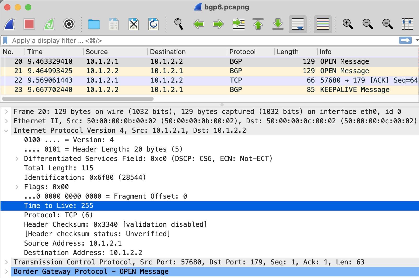
I’ve run a packet capture on the resulting session. Looking at the IP header of the BGP Open message from R1 to R2, we see a TTL of 1, as expected:
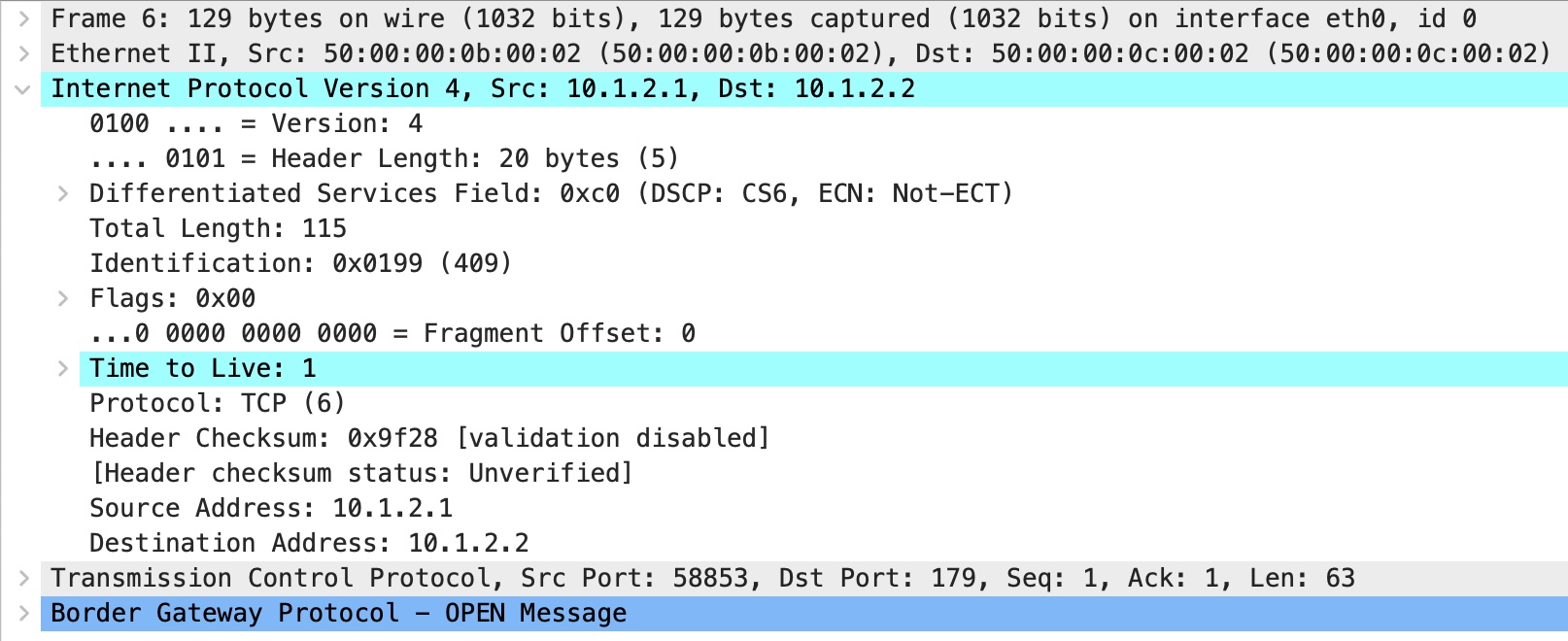
So far, so good!
Now, I’m going to delete this config, and replace it with a source and destination of the two loopbacks. Remember, you saw from the pings earlier that R1 and R2 can talk to each other’s loopback IPs.
This is the config on R1. R2 has the equivalent config:
root@R1> show configuration protocols bgp
group TO_R2 {
    type external;
    local-address 192.168.1.1;
    peer-as 65502;
    neighbor 192.168.1.2;
}
Before I commit, I start a fresh packet capture. I commit, and leave it for a few minutes:
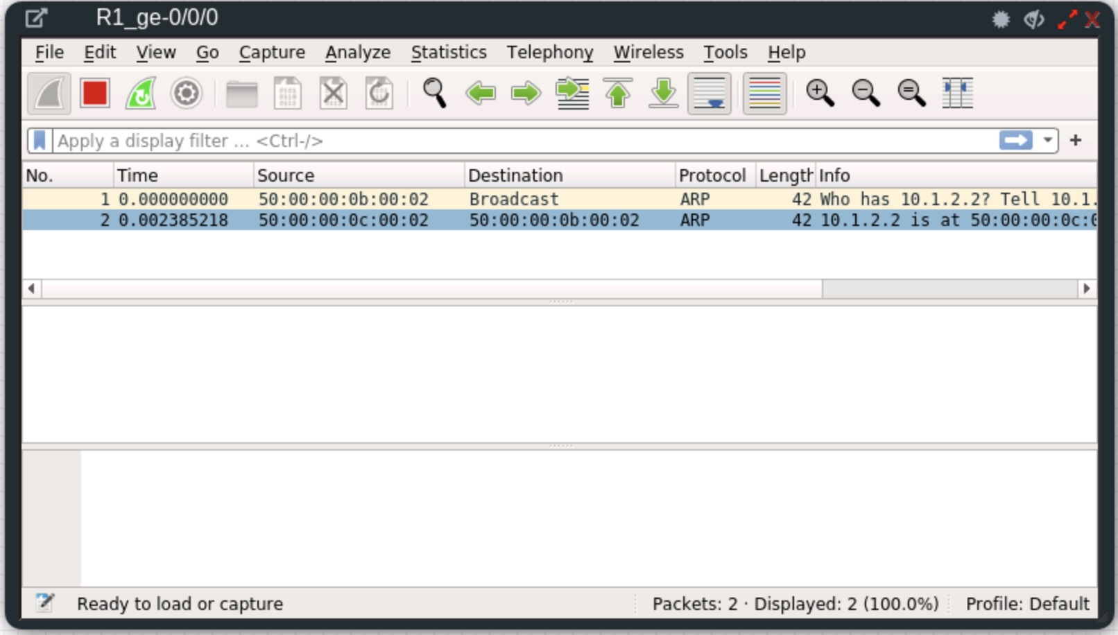
This time, all BGP messages have stopped. It seems that both routers have followed the logic we mentioned a moment ago. The neighbor is not in a directly connected subnet, and therefore the session is not even attempted.
As you would expect, both BGP sessions are in an Idle state, because they are not attempting to establish:
root@R1> show bgp summary
Threading mode: BGP I/O
Default eBGP mode: advertise - accept, receive - accept
Groups: 1 Peers: 1 Down peers: 1
Table          Tot Paths  Act Paths Suppressed    History Damp State    Pending
inet.0
                       0          0          0          0          0          0
Peer                     AS      InPkt     OutPkt    OutQ   Flaps Last Up/Dwn State|#Active/Received/Accepted/Damped...
192.168.1.2           65502          0          0       0       0          35 Idle
THE SO-CALLED EBGP MULTIHOP SOLUTION
You may already know that the solution to this is to create a so-called “multihop” peering.
Using this configuration statement, you can set the TTL to something else of your choosing. The result, as the command implies, is that you can create EBGP sessions that are multiple hops away.
Of course, in this case we are absolutely not creating a multi-hop session. The BGP session is precisely one hop away, not two. And it’s exactly this point that confuses new students when they study how the IP TTL works. I dare say that this “multihop” command has to be in the top 10 commands that confuses new students about how IP actually works.
If you were to read up on EBGP, you would learn that the TTL must be set to at least 2 for a loopback-to-loopback session to work between two directly connected devices. As such, a new student might reasonably conclude, therefore, that (for example) pings to a router’s loopback would decrement the TTL by one before the packet is processed by the loopback.
In other words, you might think that the TTL were decremented by one as soon as the packet arrives on the incoming interface, before any kind of processing. After all, why else would you need to set the TTL to 2?
In fact though, this is not the case at all. The reason for setting the TTL to 2 is to break the self-imposed rule we saw earlier. In effect, we are manually telling the router “it’s okay to make an EBGP session to this neighbor”.
CONFIGURING EBGP MULTIHOP IN JUNOS
Each vendor has their own way of configuring EBGP multihop, whether it be setting the TTL manually, or just letting your router take care of it.
Many examples from all vendors will set a TTL of 2. The reason for this is usually “security”, in that it means your session is very unlikely to accidentally travel so many hops away that an attacker could intercept.
We’ll talk more about that in a moment.
For the time being, let’s edit R1’s config to use a TTL of 2. The other router will remain unchanged:
[edit]
root@R1# set protocols bgp group TO_R2 neighbor 192.168.1.2 multihop ttl 2
What happens next?
Our packet capture shows that a TCP handshake is successful, in the first three packets. R1 sends a BGP Open message at packet 4, with a TTL of two. However, R2 rejects it with a Notification message at packet 5. The remaining packets shut down the TCP session.
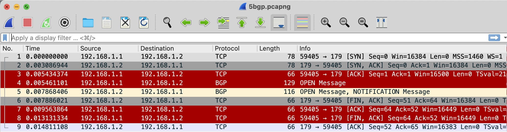
The fix, of course is to set both ends to have a multihop TTL of 2. If you do this, the session will come up.
I could configure R2 with a TTL of 2 to prove this. But instead, let’s do something “cool”.
You see, in Junos, you can configure multihop with a TTL of 1!
Let’s do this on R1:
[edit]
root@R1# set protocols bgp group TO_R2 neighbor 192.168.1.2 multihop ttl 1
And this on R2:
[edit]
root@R2# set protocols bgp group TO_R1 neighbor 192.168.1.1 multihop ttl 1
And what would you know: the BGP session comes up! Let’s filter the output to focus just on the line we care about:
root@R1> show bgp summary | match 192.168.1.2
192.168.1.2           65502          4          2       0       1          32 Establ
This proves that the TTL does not *have* to be 2 or more when you’re running EBGP between the loopbacks of two directly connected neighbors. A TTL of 1 works perfectly fine. You just need the correct configuration to make it happen.
Make no mistake about the way that the TTL field operates – it value is only decremented when it passes from one subnet to another, and from one device to another, whether that “device” be physical or virtual.
We could end this post here – but there’s one final fun thing to tell you about.
THE GENERALIZED TTL SECURITY MECHANISM
On the surface, it might seem like a good idea to set a TTL of 1 for outgoing packets. This ensures that your router will never create a connection to a device that is multiple hops away, should your network be compromised. After all, why set it to 2 when you can set it to 1, and have everything work perfectly?
It’s not a bad idea, from a security perspective. However, it turns out there’s an even bigger brain solution you can use.
Instead of a TTL of 1, what if you set the TTL to be 255 – and in addition, you configured your routers to only accept packets with a TTL of 255? A router that is genuinely multiple hops away would never be able to craft a packet like this, because the TTL would inevitably be decremented at each hop. If you receive any BGP packet on an interface with a TTL of 254 or less, you know that something isn’t right.
The name for this is the Generalized TTL Security Mechanism, or GTSM for short. It’s defined in RFC 5082, and in Junos the configuration is a three-step process.
First, you set a TTL of 255 on the EBGP peering.
The configuration changes depending on whether your peering is to a directly connected IP, or to a loopback.
If your peer is on a directly connected subnet, you configure it directly on the neighbor’s IP address:
[edit]
root@R1# set protocols bgp group TO_R2 neighbor 10.1.2.2 ttl 255
If you’re using loopback IPs, you still need to enable “multihop” because the neighbor is not on a directly connected subnet. You set the TTL under the multihop statement:
[edit]
root@R1# set protocols bgp group TO_R2 neighbor 192.168.1.2 multihop ttl 255
If you try it the first way on a loopback IP, you’ll get a commit error:
[edit]
root@R1# set protocols bgp group TO_R2 neighbor 192.168.1.2 ttl 255

[edit]
root@R1# commit and-quit
[edit protocols bgp group TO_R2 neighbor 192.168.1.2 ttl]
  'ttl 255'
    This option is valid only for single-hop EBGP neighbor
error: commit failed: (statements constraint check failed)
I’m going to use local interface IPs for this example.
Second, you create a firewall filter. For Cisco folks, IOS calls it an access list. I wrote about firewall filters here, if you want to learn how they work.
For now, here’s the syntax in set format. Notice that I block all TCP packets on port 179 that don’t have a TTL of 255. You can add in some source addresses here too, if you like:
root@R1> show configuration firewall family inet | display set relative
set filter TTL_SECURITY term BGP_NEIGHBOR from protocol tcp
set filter TTL_SECURITY term BGP_NEIGHBOR from ttl-except 255
set filter TTL_SECURITY term BGP_NEIGHBOR from port 179
set filter TTL_SECURITY term BGP_NEIGHBOR then discard
set filter TTL_SECURITY term ACCEPT_ALL_ELSE then accept
And here it is in hierarchy format:
root@R1> show configuration firewall family inet
filter TTL_SECURITY {
    term BGP_NEIGHBOR {
        from {
            protocol tcp;
            ttl-except 255;
            port 179;
        }
        then {
            discard;
        }
    }
    term ACCEPT_ALL_ELSE {
        then accept;
    }
}
Then, you apply the filter. This particular filter has been written to be applied on R1’s physical interface facing R2. Alternatively, with a bit more thought and editing, you could apply it to your lo0 interface to act directly on the control plane:
[edit]
root@R1# set interfaces ge-0/0/0 unit 0 family inet filter input TTL_SECURITY
When I save my work, I can see the TTL is indeed 255:
And the BGP session comes up:
root@R1> show bgp summary | match 10.1.2.2
10.1.2.2              65502         16         14       0       3        6:07 Establ
That’s great and all – but how do we know that this firewall filter is really protecting us from attack?
LET’S REALLY VERIFY THIS
Just to test this, let’s add a third router into the mix.
This diagram introduces R3. We’re going to make a multihop EBGP session between R1 and R3’s loopback, with a TTL of 255.
Let’s add this configuration to R1, and the equivalent on R3:
root@R1> show configuration protocols bgp group TO_R3 | display set
set protocols bgp group TO_R3 type external
set protocols bgp group TO_R3 local-address 192.168.1.1
set protocols bgp group TO_R3 peer-as 65503
set protocols bgp group TO_R3 neighbor 192.168.1.3 multihop ttl 255
When our firewall filter is not applied to R1’s ge-0/0/0 interface (the physical interface facing R2), R1 has successful EBGP sessions to both R2 and R3:
root@R1> show bgp summary
Threading mode: BGP I/O
Default eBGP mode: advertise - accept, receive - accept
Groups: 2 Peers: 2 Down peers: 0
Table          Tot Paths  Act Paths Suppressed    History Damp State    Pending
inet.0
                       0          0          0          0          0          0
Peer                     AS      InPkt     OutPkt    OutQ   Flaps Last Up/Dwn State|#Active/Received/Accepted/Damped...
10.1.2.2              65502          3          2       0       1          10 Establ
  inet.0: 0/0/0/0
192.168.1.3           65503          3          2       0       1          10 Establ
  inet.0: 0/0/0/0
However, the story changes when we re-apply our firewall filter. The session to R2 still works, because its incoming packets have a TTL of 255. However, R3’s packets have an incoming TTL of 254, and are therefore discarded:
root@R1> show bgp summary
Threading mode: BGP I/O
Default eBGP mode: advertise - accept, receive - accept
Groups: 2 Peers: 2 Down peers: 1
Table          Tot Paths  Act Paths Suppressed    History Damp State    Pending
inet.0
                       0          0          0          0          0          0
Peer                     AS      InPkt     OutPkt    OutQ   Flaps Last Up/Dwn State|#Active/Received/Accepted/Damped...
10.1.2.2              65502          8          7       0       2        2:53 Establ
  inet.0: 0/0/0/0
192.168.1.3           65503          0          0       0       2        2:56 Connect
THAT’S IT!
This stuff isn’t always well explained. Many places just go “yeah you need multihop because it’s not directly connected”, without explaining the real implications of this. No wonder so many new students get confused about how TTLs are processed by routers! Er, I mean “layer 3 devices”. Now you’ve read this post, you can have confidence about how this all works in your own network.
Hey, thanks very much for reading this! If you liked it, please share it with friends and colleagues.
Check out my older posts if you fancy learning more cool networking and Junos stuff!
If you’re on Mastodon, follow me to find out when I make new posts. (2024 edit: I’m also on BlueSky nowadays too. I was once on Twitter, but I’ve given up on it, on account of… well, I don’t need to finish that sentence, do I.)
Take care, and see you soon!


Now this predates my career by a long shot but looking into the origins of eBGP’s TTL 1 value, it looks like it was first proposed in NANOG 26 in 2002 and under IETF draft-gill-btsh-00. Referred to as “BGP TTL Security Hack (BTSH)”. BTW, there is a YouTube archive for all the sweet VHS goodness of this event and throw back with AOL branded presentations.
It looks like the authors then published RFC 3682 “The Generalized TTL Security Mechanism (GTSM)” which also referenced in Juniper’s docs under BGP’s TTL statement. What’s interesting is it was intended for broad use across various protocols.
From what I can find, this appears to be the origins and a simple attempt to reduce the extremely limited resources at the time.
Yooo thank you for your comment Ryan!
Looking at this link: https://datatracker.ietf.org/doc/html/draft-gill-btsh-00 – I can see this being the origin of the idea for using a TTL of 255, but I can’t see it as the origin of a TTL of 1. Am I misunderstanding you? Which section should I look at please?
Ooh, thank you for the YouTube tip! I found this playlist of Nanog 26: https://www.youtube.com/watch?v=hQfbWQBWOpg&list=PLO8DR5ZGla8gox24RRwhE-kgqp1A0Tij1&ab_channel=NANOG – might give a a few of them a watch. Sounds like a fun blast from the past!
Oh yeah, I should have clarified that their proposal was from the inverse perspective (Sender’s TTL=255, drop all traffic with decremented TTL). More so of it possibly being the origins leading up to TTL changes.
Sec 2.1 contains the following statement:
“Since the vast majority of our peerings are between adjacent routers,
we can set the TTL on the BGP packets to 255 (the maximum possible
for IP) and then reject any BGP packets that come in from configured
peers which do NOT have a TTL in the range 255-254.”
It’s not specifically referencing setting the TTL=1, yet putting the responsibility on the far end to filter traffic that has been routed. This would make sense if eBGP’s TTL=1 was not proposed yet and this “BGP TTL Security Hack” was done through simple ACLs.
Shortly after, the same authors (which is how I tried piecing it together) published RFC 3682 which specifically proposes a TTL=1 for a wide range of protocols. My assumption or guess (which may be widely incorrect) is their draft had traction and they thought, “What if we just set the TTL=1 and let it be handled in transit instead of dropped at the far end”.
This is all speculation though with what I could find. While a lot is irrelevant nowadays, I do love reading/listening to the history of how things came to be. I too would be interested to hear from people involved in the project on how accurate this may have been.
Edit: I retract my second to last paragraph. I broke my own rules of not double checking and did not go back to read the RFC but It does not mention TTL=1, yet proposes the same as the draft. I could have sworn I saw a brief mention of it, but I actually read the sentence wrong. My assumption still stands though yet instead of the source of my imaginary quote being the authors, it may have been the vendors (highly likely starting with Cisco)
Thanks again for taking the time to write all that 🙂
Aah that’s interesting. I had assumed that TTL = 1 came first, and TTL = 255 came later. But yeah, there’s a chance it was the opposite. Though having said that, I would bet money that the “rule” within networking OSs about EBGP neighbors came even before that. In any case though – isn’t it maddening that neither of us can actually find a definitive source on this, and we’re left to just speculate based on other RFCs? You’d think it would be written *somewhere*!