

INTERPROVIDER OPTION A, ON JUNIPER JUNOS ROUTERS (INCLUDES FULL TOPOLOGY CONFIG!) (JNCIP-SP, JNCIE-SP)
“Autonomous Systems” is the plural of Autonomous System. Looks fine written down, doesn’t it? But how do you write Autonomous Systems as an acronym? ASs? ASes? ArSes? It’s a mess, an absolute mess. We’re not even done with the first paragraph of this post, and already I’ve brought the networking world completely to its knees with this embarrassing ass-based insight. Good luck looking your partner in the eye tonight, when you have to tell them that you “administer ASes” for a living.
Anyway, forget all that: this blog is the first in a series, dedicated to the different ways you can extend an MPLS VPN over two autonomous systems.
Up until today, the only way people could get information out of an MPLS VPN in one AS and into another was by old-fashioned means. You know: like writing the packets on a bit of paper and posting them to the other ISP. Or, in one famous case, asking Barry Manilow to read out an entire file in binary during his iconic Royal Albert Hall concert in 1995. It worked, but broadcasting it to 5,000 excited soft-rock fans is hardly secure, even if no-one in the audience can actually speak binary.
Well, today that all changes. This is the first of three posts where we dive deep into the various ways that we can extend an MPLS VPN to another AS. These posts assume a basic knowledge of MPLS and Layer 3 VPNs, but don’t be scared: I’ll still try to explain the concepts as we go, so even if you’re new to it all, you’re very welcome here! And hey: if you’re just here to learn more about asses, stick around too. There’s a place at this table for everyone.
WHY WOULD WE WANT TO EXTEND AN MPLS VPN ACROSS AUTONOMOUS SYSTEMS?
Good question, if I do say so myself! And I do. I do say so myself.
There’s a few situations where this might come in handy. For example, perhaps one ISP doesn’t have a presence in every location the customer needs, so some sites will have to be hosted with a second ISP. In this situation you could run an IPsec VPN between two firewalls at the boundary of each MPLS VPN – but if you can run an interconnect between the two ISPs, there’s another way which might be easier.
Another scenario is where the MPLS VPN is global in scale, but the provider uses a different AS number in different geographical areas.
Perhaps we might even have a customer migrating form one ISP to another, but their network is too big to migrate in one go, and as such we want to extend the connectivity between the two ISPs so that we can migrate slowly, while not losing connectivity between sites.
In all of these scenarios, we’re faced with a problem: a PE router in ISP-A doesn’t often have a labelled path to the loopback of a PE router in ISP-B. After all, label-switched paths *tend* to stay within one IGP domain. So, how do we achieve this mighty ambition?
THE THREE INTERPROVIDER OPTIONS
Well, as it happens, Barry MPLS-VPN (the inventor of MPLS VPNs) foresaw this situation when he was writing RFC4364, which defined MPLS VPNs – and in his wisdom Barry suggested three possible solutions:
- A) Talk eBGP with the other ISP, but put the BGP session into the customer’s VRF itself. In other words, treat the other service provider as if they were just another customer CPE. It involves individual BGP and VRF configs for each customer, so it’s not very scalable, but it’s perfect when you have no control over the other ISP’s network.
- B) Talk eBGP with the other ISP, in the global/default routing table – but as well as the usual IPv4 and IPv6 address families, go one step further and enable the “inet-vpn unicast” family. Each ASBR advertises a unique label for every prefix in every VRF to the other ASBR, which is a bit like creating a label-switched path between the two ISPs.
- C) Run eBGP between the ASBRs again, but this time there’s no VPN unicast between them. Instead, the ASBRs run a thing called BGP Labelled Unicast, which actually allows PEs in one ISP to have a label-switched path to the loopbacks of the PEs in the other ISP!
These options are listed in the RFC in this exact order, which is why they’re referred to as option A, B, and C. If you’re hitting up Juniper’s JNCIP-SP, or indeed the JNCIE-SP, you’ll want to be very familiar with all three of them. And hey: that’s where I step in to help! Over the next three blog posts, I’ll be explaining each option, giving some examples of configuration, taking a deep-dive into the labels, and helping you to become a true master with each scenario. In this first blog post, we’ll start with Option A.
OUR TOPOLOGY EXPLAINED
It was very kind of old Barry MPLS-VPN (who you’ll remember invented MPLS VPNs, in the 17th century) to make the first option the easiest of the three to understand. Option A is where we treat the other ISP’s router as if they were just a CPE. Let’s take some time to familiarise ourselves with our topology, so that you can understand the philosophy, and maybe even try setting it up yourself. I’ve even done a ton of the config for you, so you can jump right in.
In fact, at the end of this post I’ll even share the full configs for all 10 ISP routers with you. Go on, be brave!
(If you understand what’s going on simply from looking at the network diagram here, you can skip this section.)
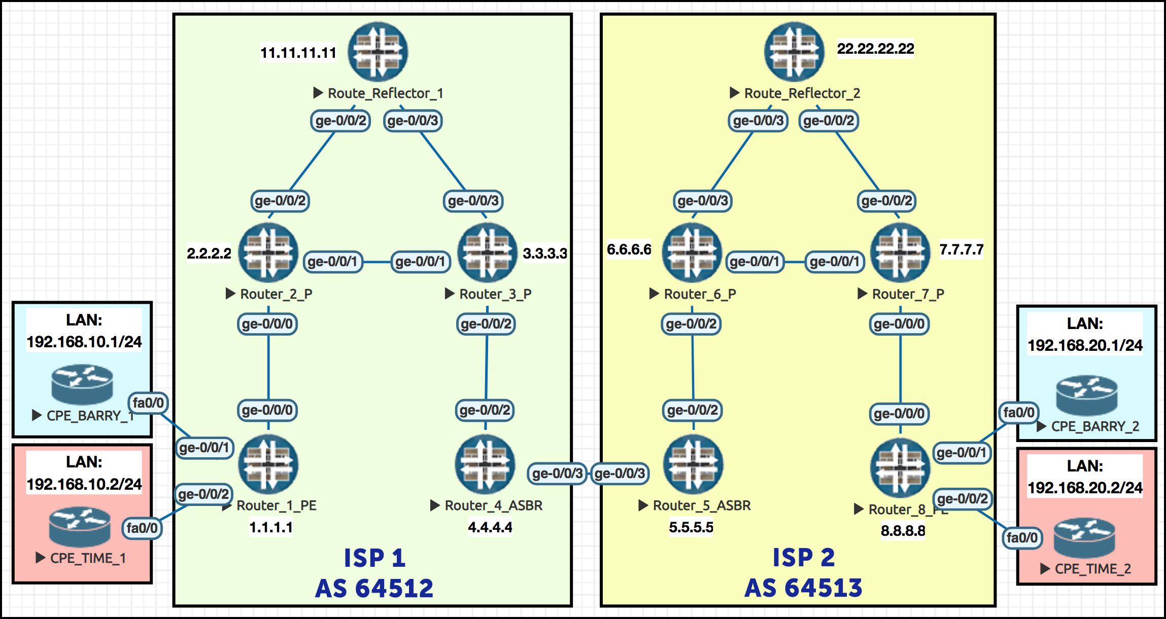
In this topology we see two customers: Barry’s Ice Cream, and Time Travel Inc. Two very different businesses, but hey: whether you make ice cream or whether you rip up the very laws of space-time itself, MPLS is for everyone.
Each customer has a VPN stretched over two internet providers. ISP1 is AS64512, and ISP2 is AS64513. If those seem like random high numbers to you, then let me teach you a cool new fact: AS numbers 64512 to 65534 are all reserved specifically for private use. So 64512 and 64513 are the first two private AS numbers. Definitely worth memorising!
In ISP 1, each customer has a site with a LAN range of 192.168.10.0/24. On the right in ISP2, each customer has another site, and this time the LAN ranges are 192.168.20.0/24. Gosh, what a coincidence! What are the chances! It’s almost like I planned all this in advance myself. By using the same LAN range for each customer, we can prove that both LAN ranges really are being advertised strictly within a VRF.
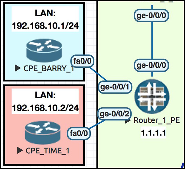 To further prove it, the CPE routers each have different IPs within that subnet, so that we can be certain our ping tests are definitely going to the correct router. For example, notice in this screenshot how the LAN interface on Barry’s CPE1 is 192.168.10.1/24. By contrast, the LAN interface on Time Travel’s CPE is 192.168.10.2/24. If we can ping Time Travel’s 192.168.10.2 from within Barry’s VRF, something has gone very wrong indeed!
Routers 1 and 8 are our PE routers. 2 and 3, and 5 and 6, are our P routers, ie our core routers. 4 and 5 are where the two ISPs interconnect – these are our ASBRs, or Autonomous System Boundary Routers. Finally, we see Route Reflectors 1 and 2 at the top, each serving their respective ISP.
The one thing we don’t see in this topology is the special secret router that I use to buy illegal coffee and watermelons from the dark web. Please don’t ask me about this router: it is none of your business.
I’ve not put many interface IPs on here, but they’re easy to remember: a thing I like to do with IP addresses in labs is use a scheme where I can immediately tell what address an interface will have. With that in mind, the numbering scheme of almost all my interfaces is 10.10.xy.x/24, where x is the first router number, and y is the second.
So for example, the link between routers 3 and 4 is 10.10.34.0/24. Router 3’s interface is 10.10.34.3/24, and router 4’s interface is 10.10.34.4/24. Almost impossible to do something as #nice as this in the real world, but hey: we’re in a lab, so let’s treat ourselves.
The routers all have loopbacks that relate to their router number, so the loopback of router 2 is simply 2.2.2.2. The exception is Route Reflector 1 and 2, whose loopbacks are 11.11.11.11 and 22.22.22.22 respectively.
CONFIGURATION – GETTING OUR ISPs SET UP
First of all, let’s get our ISP networks set up. I’m running IS-IS in ISP1, and OSPF in ISP2. For the MPLS protocol we could use any protocol we like. Let’s just use LDP in both ISPs, for the sake of simplicity. Here’s what we need to do for this lab:
— Configure IPs on all the interfaces that connect our ISP routers together
— Configure VRFs on Routers 1 and 8 for each customer
— Give the customer-facing interfaces IP addresses, and put them into the correct VRF
— Turn on MPLS and LDP, and either OSPF or IS-IS, only on interfaces that connect the ISP routers together
— Turn on BGP between our PE routers and our route reflectors.
Here’s the significant config on Router 2, to give you an example:
set interfaces ge-0/0/0 unit 0 family inet address 10.10.12.2/24
set interfaces ge-0/0/0 unit 0 family iso
set interfaces ge-0/0/0 unit 0 family mpls
set interfaces ge-0/0/1 unit 0 family inet address 10.10.23.2/24
set interfaces ge-0/0/1 unit 0 family iso
set interfaces ge-0/0/1 unit 0 family mpls
set interfaces ge-0/0/2 unit 0 family inet address 10.10.112.2/24
set interfaces ge-0/0/2 unit 0 family iso
set interfaces ge-0/0/2 unit 0 family mpls
set interfaces lo0 unit 0 family inet address 2.2.2.2/32
set interfaces lo0 unit 0 family iso address 49.0001.0000.0000.0002.00
set protocols isis level 1 disable
set protocols isis level 2 wide-metrics-only
set protocols isis interface ge-0/0/0.0
set protocols isis interface ge-0/0/1.0
set protocols isis interface ge-0/0/2.0
set protocols isis interface lo0.0
set protocols ldp interface ge-0/0/0.0
set protocols ldp interface ge-0/0/1.0
set protocols ldp interface ge-0/0/2.0
Notice that there’s no BGP in this config. We’re running a BGP free core – no BGP on our P routers! That means that in ISP1, Routers 1 and 4 both peer with Route Reflector 1. There’s no need for the P routers to hold the routing table: as long as they know where all the loopbacks are, they can help make label-switched paths between our PE and ASBR routers.
Here’s the BGP config on Route Reflector 1.
set routing-options autonomous-system 64512
set protocols bgp group AS64512 type internal
set protocols bgp group AS64512 local-address 11.11.11.11
set protocols bgp group AS64512 family inet-vpn unicast
set protocols bgp group AS64512 cluster 11.11.11.11
set protocols bgp group AS64512 neighbor 1.1.1.1
set protocols bgp group AS64512 neighbor 4.4.4.4
Notice that the presence of the cluster command is all it takes to turn this router into a route reflector. In addition, we’re turning on the inet-vpn unicast family. This actually turns off the usual inet unicast family, so if you want that too then be sure to explicitly configure it! We don’t need it for this lab though.
We definitely want two VRFs on our PE routers, one for each customer. We also want interfaces for their CPEs to plug into. All my ISP1 CPE-to-PE links have IPs in the 172.16.10.x range. ISP2’s CPE-to-PE links are 172.16.20.x. “Cool”! Here’s the relevant config from Router 1:
set interfaces ge-0/0/1 unit 0 family inet address 172.16.10.1/30
set interfaces ge-0/0/2 unit 0 family inet address 172.16.10.5/30

set routing-instances BARRYS_ICE_CREAM instance-type vrf
set routing-instances BARRYS_ICE_CREAM interface ge-0/0/1.0
set routing-instances BARRYS_ICE_CREAM route-distinguisher 1.1.1.1:1
set routing-instances BARRYS_ICE_CREAM vrf-target target:64512:1

set routing-instances TIME_TRAVEL_INC instance-type vrf
set routing-instances TIME_TRAVEL_INC interface ge-0/0/2.0
set routing-instances TIME_TRAVEL_INC route-distinguisher 1.1.1.1:2
set routing-instances TIME_TRAVEL_INC vrf-target target:64512:2
Now, when it comes to advertising the CPE’s LAN back to the PE (ie Routers 1 and 8), we have two options: static routes on the PEs, or run a routing protocol between both PE and CPE. To keep the config short and simple I’ve just configured a static route within the VRF on the PE, pointing to the CPE LAN. In the return direction, each CPE has a static default route back to the ISP.
Let’s add these two lines to Router 1:
set routing-instances BARRYS_ICE_CREAM routing-options static route 192.168.10.0/24 next-hop 172.16.10.2
set routing-instances TIME_TRAVEL_INC routing-options static route 192.168.10.0/24 next-hop 172.16.10.6
LET’S CONFIGURE INTERPROVIDER OPTION A!
So, now we have two customers with MPLS VPNs in ISP1, and those same customers with MPLS VPNs in ISP2. If you’re already familiar with Layer 3 MPLS VPNs then so far it’s nothing you haven’t seen before. Our final task is to add the special config between Routers 4 and 5.
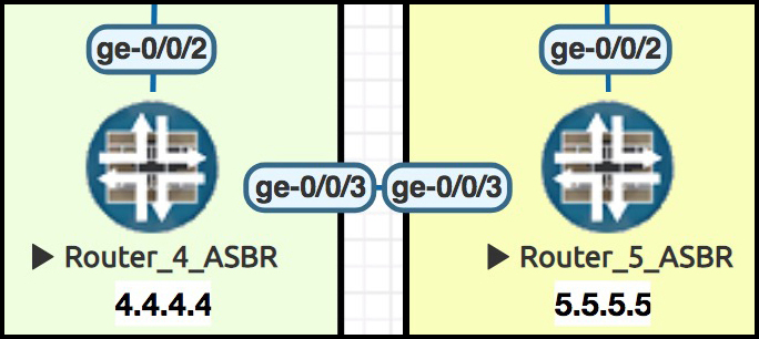 We already have a physical cable running between Routers 4 and 5. Well, not physical-physical: this is all just virtualised, aka make-believe. It’s merely a figment of a computer’s imagination. A fantasy, a whimsical fantasy. But you know what I mean.
Here’s what we’re going to do next:
— We’re going to sub-interface this link into two logical interfaces;
— Give each sub-interface an IP and a VLAN tag;
— Define each customer VRF on Routers 4 and 5, manually;
— Put a sub-interface into each VRF;
— And finally, run two BGP peerings between Routers 4 and 5, each within a VRF.
Before we configure all that though, it’s worth thinking about what we’re achieving by doing this.
Usually, MPLS labels give us the ability to run two or more VPNs that use private and overlapping IP address space, because we’re forwarding on the label rather than the IP address. But in this situation, there is no MPLS between the two routers. That’s why we’re using VLAN tags to distinguish the traffic – and crucially, we’re putting the tagged sub-interfaces directly into the VRF. Technically these interfaces are our own infrastructure interfaces, and of course usually these wouldn’t be put into a customer’s VRF. However, these peer-facing interfaces are an exception: even though they’re still our own infrastructure interfaces, in actual fact we’re treating them as if they’re CPE-facing.
In that respect, you could argue philosophically that although Interprovider Option A extends the VPN, it doesn’t strictly extend the MPLS VPN. Rather, it ends the MPLS VPN at the egress interface of Router 4, and starts a brand new MPLS VPN at the ingress interface of Router 5. The VPN itself kind-of carries on, but the MPLS piece has a very clear demarcation. No MPLS labels are exchanged between ISP1 and ISP2; instead, traffic is tagged with our pre-agreed VLAN tags. In a way, it’s almost like the traffic is still labelled!
Here’s the config for ge-0/0/3 at Router 4. The final octet is a bit of an exception to my usual “last octet = router number” rule, because we’ve got multiple interfaces going across it:
set interfaces ge-0/0/3 vlan-tagging
set interfaces ge-0/0/3 unit 10 vlan-id 10
set interfaces ge-0/0/3 unit 10 family inet address 10.10.45.1/30
set interfaces ge-0/0/3 unit 20 vlan-id 20
set interfaces ge-0/0/3 unit 20 family inet address 10.10.45.5/30
set routing-instances BARRYS_ICE_CREAM interface ge-0/0/3.10
set routing-instances TIME_TRAVEL_INC interface ge-0/0/3.20
Actually, something interesting happens here. Bearing in mind that we’ve not configured Router 5 yet, let’s take a look at Router 1’s routing table for Barry’s Ice Cream. (Oh god, just as I type those words I have a sudden moment of clarity where I ask myself why I’m writing this blog post instead of just eating some ice cream. I think I just did subliminal advertising on myself.)
Anyway, let’s see if the 10.10.45.0/30 range between Router 4 and Router 5 is in Router 1’s routing table:
root@Router1> show route table BARRYS_ICE_CREAM.inet.0

BARRYS_ICE_CREAM.inet.0: 3 destinations, 3 routes (3 active, 0 holddown, 0 hidden)
+ = Active Route, - = Last Active, * = Both

172.16.10.0/30     *[Direct/0] 06:36:16
                    > via ge-0/0/1.0
172.16.10.1/32     *[Local/0] 06:36:38
                      Local via ge-0/0/1.0
192.168.10.0/24    *[Static/5] 06:36:16
                    > to 172.16.10.2 via ge-0/0/1.0
Hmm, it isn’t. That’s odd. The interface on Router 4 is definitely up:
root@Router4> show interfaces terse ge-0/0/3
Interface               Admin Link Proto    Local                 Remote
ge-0/0/3                up    up
ge-0/0/3.10             up    up   inet     10.10.45.1/30
ge-0/0/3.20             up    up   inet     10.10.45.5/30
Is Router 4 even advertising this prefix to our route reflector?
root@Router4> show route advertising-protocol bgp 11.11.11.11

BARRYS_ICE_CREAM.inet.0: 4 destinations, 4 routes (4 active, 0 holddown, 0 hidden)
  Prefix		  Nexthop	       MED     Lclpref    AS path
* 10.10.45.0/30           Not advertised               100        I

TIME_TRAVEL_INC.inet.0: 4 destinations, 4 routes (4 active, 0 holddown, 0 hidden)
  Prefix		  Nexthop	       MED     Lclpref    AS path
* 10.10.45.4/30           Not advertised               100        I
Aah, look at that – Router 4 is indeed advertising it, but with no next-hop! What’s going on?
Well, it turns out that in Junos, this is the default behaviour. Here’s the concept: On a PE router, prefixes on a directly-connected interface in a VRF are only advertised when they’re being used as a next-hop for another prefix. In other words, at the moment 10.10.45.0/30 (and 10.10.45.4/30 from the other VRF) aren’t valid in BGP.
But don’t fear: when we set up Router 5 and we run BGP between the two routers, Router 5 will advertise prefixes to Router 4, and so the /30 between Routers 4 and 5 will indeed be advertised everywhere. And if this default behaviour is no good for you, give this KB article a read to find out three ways to get around it!
TESTING!
I went ahead and configured Router 5 in the same way. Now, let’s see if it works. There’s one simple way to test this: let’s go to Barry’s CPE 1, and try to ping Barry’s CPE 2:
CPE_BARRY_1#ping 192.168.20.1

Type escape sequence to abort.
Sending 5, 100-byte ICMP Echos to 192.168.20.1, timeout is 2 seconds:
!!!!!
Success rate is 100 percent (5/5), round-trip min/avg/max = 108/128/152 ms
Success! And just to check that everything is working right, let’s try to ping Time’s CPE 2, from Barry’s CPE 1:
CPE_BARRY_1#ping 192.168.20.2

Type escape sequence to abort.
Sending 5, 100-byte ICMP Echos to 192.168.20.2, timeout is 2 seconds:
.....
Success rate is 0 percent (0/5)
Good times! We clearly have routes in both directions; our route reflection is working perfectly; and Routers 4 and 5 are the best of friends. Let’s take a look at the routing table in Router 1, just to be absolutely sure that everything is now there as it should be:
root@Router1> show route table BARRYS_ICE_CREAM.inet.0

BARRYS_ICE_CREAM.inet.0: 6 destinations, 6 routes (6 active, 0 holddown, 0 hidden)
+ = Active Route, - = Last Active, * = Both

10.10.45.0/30      *[BGP/170] 00:01:23, localpref 100, from 11.11.11.11
                      AS path: I
                    > to 10.10.12.2 via ge-0/0/0.0, Push 299920, Push 299808(top)
172.16.10.0/30     *[Direct/0] 06:51:17
                    > via ge-0/0/1.0
172.16.10.1/32     *[Local/0] 06:51:39
                      Local via ge-0/0/1.0
172.16.20.0/30     *[BGP/170] 00:01:23, localpref 100, from 11.11.11.11
                      AS path: 64513 I
                    > to 10.10.12.2 via ge-0/0/0.0, Push 299920, Push 299808(top)
192.168.10.0/24    *[Static/5] 06:51:17
                    > to 172.16.10.2 via ge-0/0/1.0
192.168.20.0/24    *[BGP/170] 00:01:23, localpref 100, from 11.11.11.11
                      AS path: 64513 I
                    > to 10.10.12.2 via ge-0/0/0.0, Push 299920, Push 299808(top)
Awesome. We see 192.168.10.0/24, which is the route that lives out of the CPE that’s directly connected to us – but we also see 192.168.20.0/24, which is the LAN IP range over in ISP2. And look: there’s that 10.10.45.0/30 prefix that was missing before! What a happy ending.
WHEN WOULD YOU USE THIS?
Interprovider Option A is perfect in any situation where the other autonomous system is owned by a completely different company. You have no trust relationship with them, and you certainly don’t want to start exchanging labels. We simply treat the router at the ISP end of the link as if it were yet another CPE – though admittedly, a CPE hosting a far bigger network than the average CPE!
In fact, I found out recently that colleagues of mine had been using it without even realising what it was called! I work at an ISP, and it’s not uncommon for customers to either migrate to us or away from us. In these situations we need to run an interconnect between us and the other ISP to connect the two private networks together, but of course we don’t trust anything about the other ISP’s network. We don’t want to run OSPF/IS-IS with them, nor do we want to run MPLS. Interprovider Option A to the rescue!
THINGS TO BEAR IN MIND – COMMUNITIES
When a Juniper router talks eBGP, it doesn’t remove any of the communities attached to a prefix. Take a look at the extensive output of a prefix that Router 5 learned from Router 4 within the BARRYS_ICE_CREAM VRF:
root@Router5> show route table BARRYS_ICE_CREAM.inet.0 192.168.10.0/24 extensive

BARRYS_ICE_CREAM.inet.0: 6 destinations, 6 routes (6 active, 0 holddown, 0 hidden)
192.168.10.0/24 (1 entry, 1 announced)
TSI:
KRT in-kernel 192.168.10.0/24 -> {10.10.45.1}
Page 0 idx 0 Type 1 val 93812b4
    Flags: Nexthop Change
    Nexthop: Self
    Localpref: 100
    AS path: [64513] 64512 I
    Communities: target:64512:1 target:64513:1
Path 192.168.10.0 from 10.10.45.1 Vector len 4.  Val: 0
        *BGP    Preference: 170/-101
                Next hop type: Router, Next hop index: 581
                Address: 0x934ca30
                Next-hop reference count: 5
                Source: 10.10.45.1
                Next hop: 10.10.45.1 via ge-0/0/3.10, selected
                State:
                Peer AS: 64512
                Age: 1:13
                Task: BGP_64512.10.10.45.1+179
                Announcement bits (2): 0-KRT 1-BGP_RT_Background
                AS path: 64512 I
                Communities: target:64512:1
                Accepted
                Localpref: 100
                Router ID: 10.10.45.1
Hello hello hello: what’s this “target:64512:1” community all about? That’s the community for the VRF in ISP1! The community hasn’t been stripped, and has been passed onto ISP2.
This default behaviour of keeping all communities over an eBGP peering is often useful, because you often do want communities to be passed from one AS to another. We’ve talked before about how many ISPs publish a list of communities their peers can use to influence traffic in certain ways.
In addition, while it’s REALLY BAD to thoughtlessly pass target communities (or indeed, any communities!) between you and another ISP, in reality it will probably be harmless, for the simple reason that almost everyone’s communities start with the AS number of the ISP itself.
But just because it will probably be fine doesn’t mean that you should pass them over anyway. Especially if you’re using communities that refer to the private AS space, because there’s a far higher chance that the other ISP is too!
PROTIP: Pop an export policy on your BGP config to strip any communities before advertising them to the other ISP, unless you’ve agreed in advance with the other ISP to keep your communities, for example so that you can both quickly identify any prefixes that came from the other ISP. In which case, leave them as they are!
THINGS TO BEAR IN MIND – SCALABILITY
Second of all, because we have to configure an eBGP peering per-customer, it’s not a very scalable solution.
In the olden days the reason for this would have been the hit to the control plane’s processor/the router’s RAM/etc, in establishing and maintaining a BGP session and routing table for each customer. To be honest, nowadays this isn’t as much of a concern. If you’re an ISP, chances are that your ASBR can handle a fair few BGP sessions, and a fair few prefixes. Unless you’re a gigantic carrier hosting many hundreds of peerings! Or unless you’re running legacy hardware are your edge, in which case you possibly have bigger problems on your plate.
(Side-note: it’s so fascinating to see how far networking as come, and how many of the old restrictions don’t really apply any more, like how older books will tell you to never have more than like 100 routers in an OSPF/IS-IS area, whereas nowadays the books say “yeah, a few thousand is probably fine tbh”.)
But you do still have to configure it all manually, including the creation of the VRF on the ASBR. And even if you have some nice automation in place, it’s still a pain. For every new customer you add, you have to create more configuration, possibly at multiple ASBR links, and it’s a lot of config and state to maintain. Wouldn’t it be great if we could just let BGP take care of every single bit of it, automatically?
Well, stay tuned, because in next week’s post we’ll learn how Interprovider Option B does exactly that!
FREE CONFIGS!
You want the config to all 10 routers in this topology? Sure thing! Click here: https://www.networkfuntimes.com/media/configs/2019/Interprovider_Option_A_Config.txt
THAT’S IT!
We’ve set some good groundwork in this post for our upcoming posts on Option B and C. Save the topology, print it, and frame it. Maybe laminate it and take it to bed at night, to give it a little cuddle. Use the topology as a pillow, and become a networking expert in your sleep.
In next week’s post we’ll look at how to configure Option B – and when we do, we’ll compare what the labels look like between Options A and B, so we get a truly deep understanding of what’s going on.
If you’re on Mastodon, follow me to find out when I make new posts. (2024 edit: I’m also on BlueSky nowadays too. I was once on Twitter, but I’ve given up on it, on account of… well, I don’t need to finish that sentence, do I.)
And if you really enjoyed this post you’d make my day if you shared it on your social media of choice – Twitter, LinkedIn MySpace, Friends Reunited, anywhere you like.
If you fancy some more learning, take a look through my other posts. I’ve got plenty of cool new networking knowledge for you on this website, especially covering Juniper tech and service provider goodness.
It’s all free for you, although I’ll never say no to a donation. This website is 100% a non-profit endeavour, in fact it costs me money to run. I don’t mind that one bit, but it would be cool if I could break even on the web hosting, and the licenses I buy to bring you this sweet sweet content.


Just nitpicking, but I believe the following is incorrect:
“For simplicity I’ve just configured a static route within the VRF to the remote CPE LAN.”
It’s not the static route to “remote” CPE LAN, but the one locally (directly) connected. Maybe it’s just me, but when you say “remote”, I immediately think of the CPE connected to R8. Or maybe I just got the whole thing wrong lol.
Sorry for the very slow reply! A good point. I’ve changed the wording, hopefully it’s a little bit clearer now. Thank you!
Great blog and great article, Chris.
Got a question though. I noticed you have BGP configured on Router3, which is a P router. Shouldn’t there be no BGP configured for P routers?
Thanks!
Haha yeah you’re right, I forgot to remove it! It’s not doing any harm being on there, and some networks do indeed run BGP on the P routers for various reasons, but in this particular scenario it’s not needed. You can safely delete that bit of the config in your lab. Well spotted, thank you!
Nice post!. I was wondering if this option is usable for L2VPN when having multiple frontiers (multiple ASBRs to the other AS)? I am thinking about the need for some kind of mechanism for loop prevention.. but I don’t figure out if it is posible..
Hi there Meyo!
Theoretically it’s usable, though I suppose it depends on the use-case. But in theory, if you were to have multiple layer 2 VPNs around the place in the way you’re describing, then you’d definitely want to run spanning tree over it. Regardless of whether it’s between ASNs or in the same ASN, ultimately there’s no inherent loop prevention in a pseudowire – just like there isn’t in an actual wire. It’s up to us to run a loop prevention protocol over it if necessary.