

JUNOS: MPLS SELF-PING, ON JUNIPER ROUTERS
In today’s post we’re going to talk about RSVP backup paths, Make-Before-Break, and most importantly, something called “MPLS Self-Ping”.
By contrast, what we’re not going to talk about in today’s posts are topics such as the Gulf Stream, French New-Wave Cinema, or where you can buy the most delicious espresso in town.
Hopefully those two introductory sentences have given you enough information to decide if you want to keep on reading. Want to learn about MPLS Self-Ping? Read on, friend! Want to learn who’ll pour you the smoothest coffee you’ve ever let glide down your throat? Log off. Log off of my website immediately. I cannot stress how important it is that you log the heck off of my web-site, right this instant. I will call the FBI if you read even a single word more of this blog. This is clearly not a coffee blog I’m running here. It’s called Network Fun-Times for goodness sake. Why are you here if you’re after coffee advice? Stop wasting my time. Stop it. Stop it now. I can’t believe I’m this angry so early into the post.
Anyway, forget every single word of what I just said. Instead, let me show you what happened to me recently.
Imagine a very simple Junos LSP from Router 1 to Router 10 (we’ll look at a network diagram in a moment), configured like this:
protocols {
     mpls {
          label-switched-path R1_TO_R10 {
               to 192.168.1.10;
               fast-reroute;
}}}
This config should create one single LSP, right? And indeed it does – to begin with. But what if one day you look in your network and you see not one LSP like you’ve seen every other time you check, but two LSPs with exactly the same name?
root@vMX_1> show rsvp session ingress
Ingress RSVP: 2 sessions
To              From            State   Rt Style Labelin Labelout LSPname
192.168.1.10    192.168.1.1     Up       0  1 SE       -   300576 R1_TO_R10
192.168.1.10    192.168.1.1     Up       0  1 SE       -   300112 R1_TO_R10
Total 2 displayed, Up 2, Down 0
These two LSPs share a name, but have different labels pushed on the packet as they go down the path, so they’re clearly different. And yet… they’re the same? This exact scenario happened to me recently, and in this post I’ll show you why it happened, and how to prevent it.
The concept of “fast-reroute” (or at least “local repair”) is required knowledge for understanding this, so I’ve taken a bit of time to explain them below. If you feel like you know these topics already, you can skip those sections if you like. Hopefully this help all readers to follow along with how MPLS Self-Ping is involved in this interesting mystery.
And then after that, later on in this post I’ll tell you all about Caffè Molto Bene, a remarkable new indie pop-up diner that serves just about the most rich and full-bodied espresso I’ve ever….
……GODDAMNIT.
OUR TOPOLOGY TODAY
Regular readers will recognise this handsome beast: it’s my famous Ten Router Topology. All the pics in this post can be clicked for full-size, so click below if you want to open it in a separate tab. Might be easier to follow along if you do:
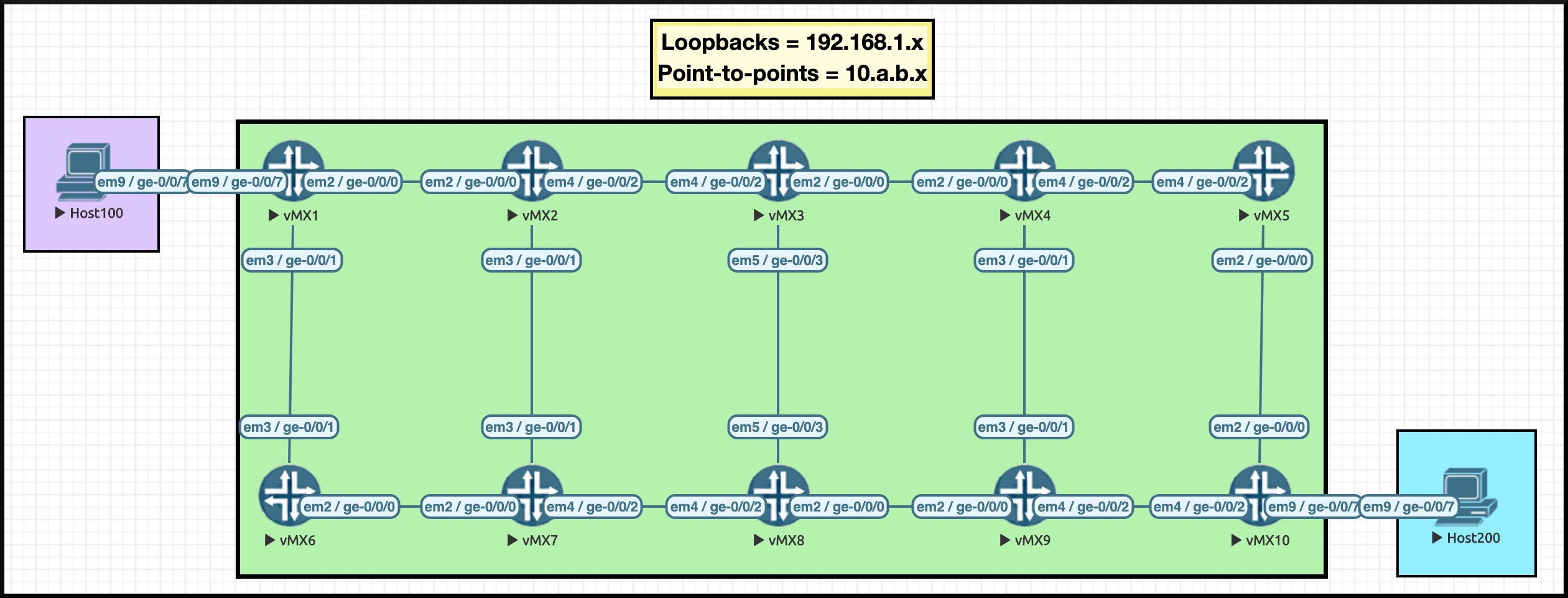
I’ve carefully chosen an IP scheme that allows us to see exactly what router we’re on. For example, Router 3’s loopback is 192.168.1.3. See the final octet? It’s a three! Another example: see how Router 3 has a connection to Router 4? The IP on Router 3’s interface is 10.3.4.3. The IP on Router 4’s interface is 10.3.4.4. Thanks to this addressing scheme, we’ll be able to read an LSP’s explicit path really easily.
Router 1 and Router 10 talk BGP to each other, and are advertising the directly-connected ranges 10.1.100.0/24 and 10.10.200.0/24.
No other core router talks BGP. In other words, we are running a BGP-free core. When Host 100 talks to Host 200, the packet should come into Router 1, and then go down a label-switched path to Router 10. If there’s no LSP then the traffic will fail, because no other routers in the network are learning these IP addresses. They’ll have no route to the traffic, so the packet will be dropped.
I only have two LSPs configured: one from R1 to R10, and one in reverse, from R10 to R1. I’ve actually manipulated the metrics somewhat to force the traffic a certain way. When the network is working correctly:
- R1 to R10 will take the top path: R1–>R2–>R3–>R4–>R5–>R10
- R10 to R1 will take the bottom path: R10–>R9–>R8–>R7–>R6–>R1
On Router 10, the LSP is configured with one single line of config:
set protocols mpls label-switched-path R10_TO_R1 to 192.168.1.1
However, on Router 1’s LSP I’m going to add an extra line of config:
set protocols mpls label-switched-path R1_TO_R10 to 192.168.1.10
set protocols mpls label-switched-path R1_TO_R10 fast-reroute
This is a very deliberately bare-bones config, so that we can really focus in on the bits we’re interested in. Of course, in the real world your network will look very different, and have far more configuration on it!
What does that “fast-reroute” command do? The answer to that question is a blog post all of its own. And as it happens, I’m actually working on exactly that post! Keep an eye out for it. But just so you can follow along, let’s briefly explain what RSVP local-repair is.
FAST RE-ROUTE (OR AT LEAST, JUNIPER’S DEFINITION)
We all remember the original title for Fifty Shades of Grey: “RFC4090: Fast Reroute Extensions to RSVP-TE for LSP Tunnels“. In retrospect, it’s probably a good job they changed it. “Fifty Shades of Grey” is a far more marketable title, and besides, neither the book nor the films really dealt very much at all with the concept of temporarily protecting RSVP-signalled LSPs from failure. Perhaps if they had, the franchise might have made more of an impact on our culture. Truly, an opportunity missed.
By contrast though, RFC 4090 can very appropriately take the name “Fast Reroute Extensions to RSVP-TE for LSP Tunnels”. With the benefit of hindsight, the authors of this RFC definitely made the right choice on the title of this one.
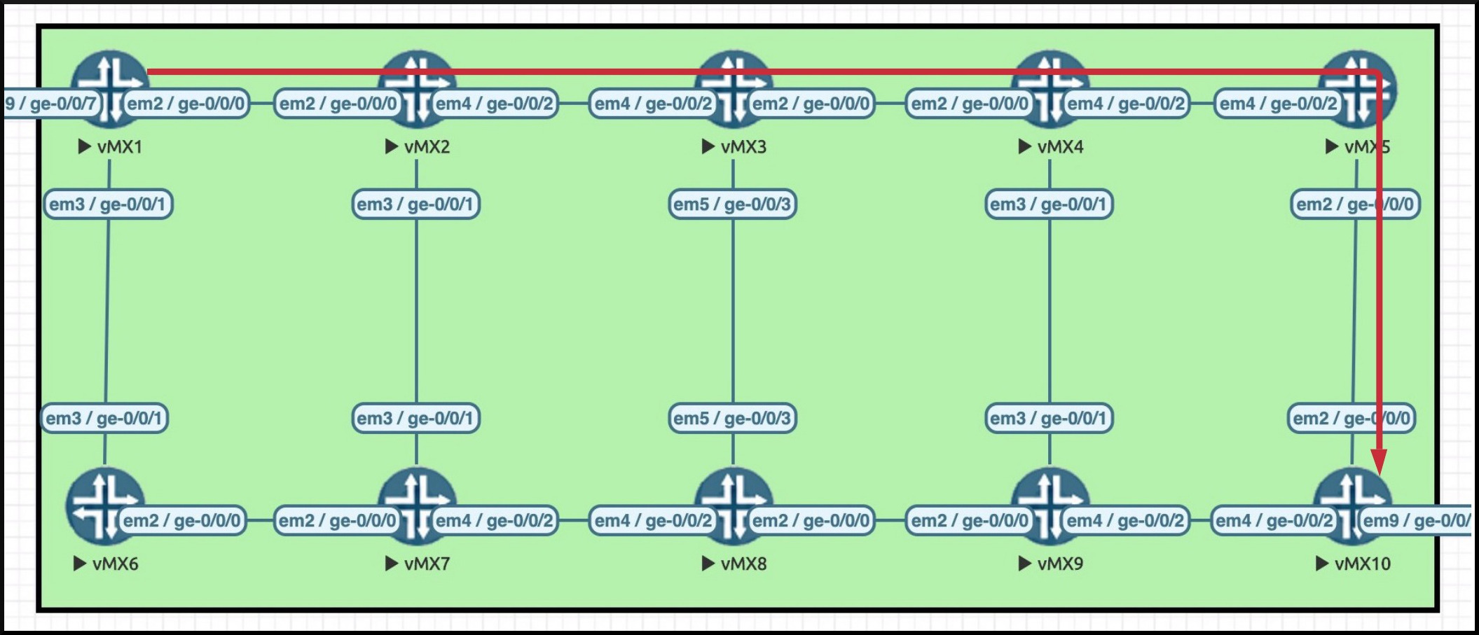
What are these extensions exactly? Here’s the concept. Let’s draw out the path of the LSP we configured from Router 1 to Router 10. You’ll see the path in the pic here, marked in red.
Now, what happens if there’s a break in the cable between Router 3 and Router 4? On a plain LSP, Router 3 would send a ResvTear message back to Router 1, informing Router 1 (and all the routers in between) that the LSP needs to be torn down, and that Router 1 needs to calculate a new alternative path.
When Router 1 receives this message, one of three things can happen, depending on how it’s configured:
- If Router 1 has pre-signalled a Secondary LSP, Router 1 will try to move traffic over to that alternative path ASAP.
- If Router 1 is configured with a Secondary LSP, but the LSP isn’t pre-signalled, Router 1 will try to calculate this Secondary path, and then create it.
- If Router 1 isn’t configured for a Secondary LSP, it will calculate an alternative Primary path, and then create it.
The difference between options 2 and 3 is that on Secondary paths, Juniper routers try to avoid links that the original path took. Once again, there’s more to it than that, and it’s a topic that we could write an entire post on! So we’ll leave it there for now, but hey: leave a comment below if you’d like a deeper dive sometime into how Primary/Secondary paths work.
That’s all good, but here’s the rub: the message from Router 3 doesn’t get to Router 1 immediately. There’s a delay while the teardown message propagates between the two routers. You can imagine that in this topology, that delay is fairly brief. But in a larger topology, or a geographically more distant topology, the delay could be much longer.
During the time that Router 3’s ResvTear message is making its journey, Router 1 will continue to send packets, which will indeed arrive at Router 3 – at which point they are dropped, discarded like an empty crisp packet, or an abandoned dog.
In a way this is a shame, because theoretically Router 3 could temporarily pass the packets to Router 8, who could then send it on its way to Router 10. But at the moment this isn’t possible, because there is no label-switched path this way. And at the moment, Router 8 has no idea of the 10.10.200.0/24 prefix, so an LSP would be mandatory. for this to work at all.
This is where the “fast reroute” extensions come into play.
RFC4090: FUN FOR ALL THE FAMILY
RFC4090 actually defines two significantly different ways that routers along the path of an LSP could create a kind of backup LSP, that can be used just during the short time that traffic is still being sent by Router 1 to Router 3, and just until Router 1 (ie the head-end) has calculated and signalled a new path to Router 10.
In a future post, we’ll talk about these two different methods in detail. For now, let’s just focus in on what Juniper calls “fast-reroute”. Cisco engineers, please note: this term means something different on your vendor of choice! In Juniper terminology, “fast-reroute” is what the RFC calls “One-To-One Backup.”
In the One-To-One Backup method, each router along the path of an LSP signals its own “detour” LSP, that goes from itself, directly to the egress router. Each “detour” is unique to the LSP being protected, and each router in the path creates one.
For example, imagine our LSP between Routers 1 and 10. In the diagram below you can see that each router is signalling an alternative “detour” path, that goes straight to the egress router. Router 1 signals a detour path that goes down to Router 6–>7–>8–>9–>10. Router 2 makes another detour, that goes down to Router 7–>8–>9–>10; Router 3 makes a detour too; and so on.
In the diagram below I’ve drawn these detour paths in orange as dotted lines. Notice that a separate detour comes off of each router that the original LSP crosses. Notice as well that Router 5’s detour actually goes backwards one hop.
From the way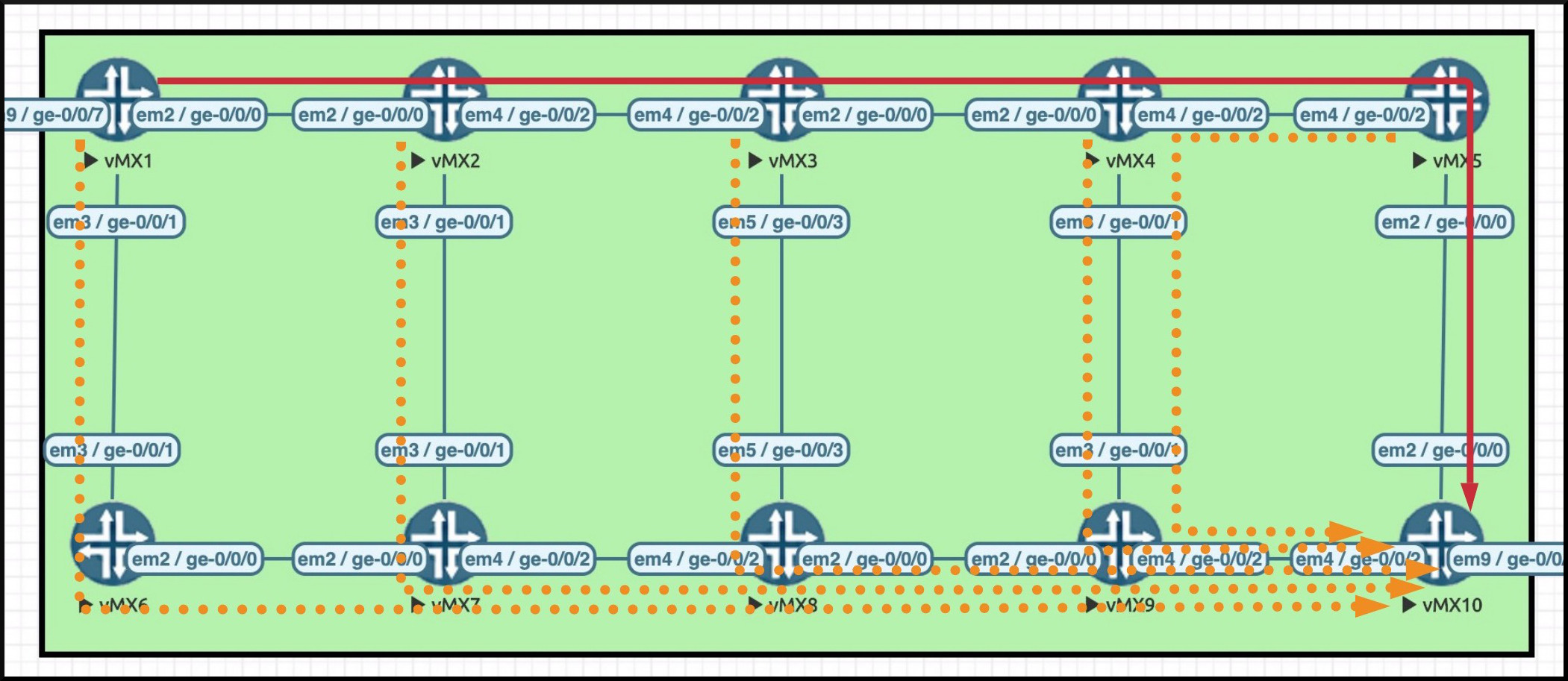 I’ve drawn this, it looks like Router 7 has two detour LSPs coming into it from Routers 2 and 6, which both go out towards Router 8. Actually though, Router 7 does something clever: it sees that these are two detours for the same LSP, and as such Router 7 merges them into one when it signals the detour on to Router 8. I’ve just drawn them as two separate detours here to help you to understand that each of these paths is destined to the egress router.
Router 8 does the same thing, merging the LSPs coming in from Router 7 and Router 3. This saves session state, but it does still mean that you’ll see the “R1_TO_R10” LSP on every single box, and you’ll never know if it’s a legit LSP or a detour, at least not without digging into the extensive output. Check out Router 7:
root@vMX_7> show mpls lsp transit
Transit LSP: 2 sessions, 1 detours
To              From            State   Rt Style Labelin Labelout LSPname
192.168.1.1     192.168.1.10    Up       0  1 FF  300000   299920 R10_TO_R1
192.168.1.10    192.168.1.1     Up       0  1 SE  300032   300032 R1_TO_R10
Total 2 displayed, Up 2, Down 0
Why is it called One-To-One Protection? Just like the name suggests, the detour is unique to the LSP. Each LSP has its own detour. One LSP, one detour. If I created a second LSP from Router 1 to Router 10, each router would create a new detour for this second LSP. Even if the LSP went across exactly the same path, the two detours for the two LSPs would be signalled and maintained separately. You can imagine that this creates a lot of extra state in the network.
Now, here’s where this all gets good. Imagine that the link between Router 3 and Router 4 goes down. Now that we have a pre-signalled detour path, Router 3 now has a new option. Instead of totally tearing down the LSP, Router 3 can instead just send an informational “PathErr” message back to R1. This message doesn’t actually tear the LSP down’; it just tells Router 1 that something’s gone wrong, and that Router 1 should try to calculate a new path. Router 1 can carry on sending traffic in the mean time.
Thanks to this detour, traffic will, in the short term, carry on going down part of the “original LSP”, from Router 1 to Router 2 to Router 3 – at which point, Router 3 will switch the traffic down its pre-signalled detour path, and Router 3 will carry on doing this until Router 1 itself has calculated and signalled a new path. Router 1 can then move the traffic over to the new path, and then tear the old path down.
THE NEED FOR MPLS SELF-PING
Now let’s talk about another standard: RFC7746, “Label Switched Path (LSP) Self-Ping”.
This one is pretty simple to understand: if MPLS Self-Ping is turned on, the router will send a packet down an LSP, with a destination address of its own loopback.
This is actually really clever: by getting a router to send a packet down an LSP with itself as the destination address, it means that it doesn’t matter if the other end understands what MPLS Self-Ping is. The egress router will simply look up the packet’s destination, and forward the packet right back to the originating router. This packet may or may not go down another label-switched path of some kind on its return journey. In fact, because the destination is a loopback of a core router, with an IP that was probably learned by IS-IS or OSPF, chances are that it will be routed back as a plain IP packet! It doesn’t matter: all that matters is that traffic returns home.
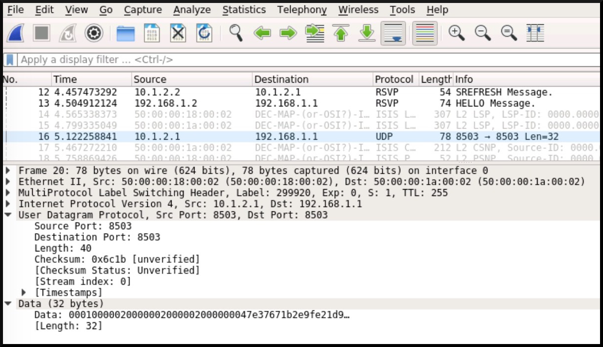
Despite the name containing the word “ping”, this is actually a UDP packet, on port 8503, as we can see in this screenshot below. Notice as well that the destination address is 192.168.1.1 – the loopback of Router 1.
Why is this process helpful? Imagine that an LSP is being established. A PATH message is successfully sent by Router 1 to Router 10, and a RESV message was successfully sent in the reverse direction, over the same links, back to the head-end. As the RESV message goes from egress to ingress, each box learns the label it should use when sending traffic to the next-hop.
Let’s go back to our topology, and focus in on Router 3.
This router receives a RESV message from Router 4, and this triggers Router 3 into performing a certain task: Router 3 now needs to pick a spare label that it’s going to tell Router 2 to use to indicate that traffic belongs to this LSP. Let’s say that this is label X, so that we can feel like some kind of dark superhero.
Once Router 3 has decided that it wants Router 2 to use label X, Router 3 needs to do two things:
- Router 3 needs to install something in its forwarding table that says “if you receive a packet with label X, swap it for label Y and send it out of interface Z”.
- Router 3 needs to send the RESV message on to Router 2, including the fact that Router 2 should use label X for this LSP.
If you’ve done JNCIS-SP, all of that will ring a bell with you, though you might not have had to think about it in that level of detail in a while.
Now, according to RFC7746, there’s an “optimization” that some vendors do to speed things up, where they’ll send the RESV message before installing this label into the forwarding table. I guess the idea is that installation into the forwarding table isn’t instant, so if Router 3 had to keep Router 2 waiting then there’d be delays around the network. Realistically, by the time the RESV message has got all the way back to Router 1, most if not all of the routers in the path will probably have installed the forwarding entry correctly.
Probably. But not definitely. And if this doesn’t happen in time, we could see some dropped packets.
Imagine that somehow the final RESV message gets all the way to Router 1. Imagine that Router 1 is somehow able to install the forwarding entry into hardware quicker than Router 3 was, perhaps because Router 1 is a more powerful box, or perhaps just because Router 1 is more confident and handsome. In any case, in this situation Router 1 could actually start forwarding traffic before Router 3 is able to process it. In this situation, traffic would be temporarily black-holed.
RFC7746 proposes a simple solution: send a message that’s a bit like a ping, from ingress to egress – but as we said earlier, instead of using ICMP, this “ping” uses UDP 8503. And as we saw in that packet capture, both the source and the destination of this packet will be the ingress router. So although it’s being “sent” to the egress router, really it’s like a boomerang packet that is sent out by a router, but comes right back to the same router again. Hence the name Self-Ping!
If Router 1 receives this MPLS Self-Ping then we can be sure that the LSP is up and working, and ready to forward traffic. Sounds good, right? As it happens, as of Junos 16.1, MPLS Self-Ping is on by default. And as it happens, Make-Before-Break uses the results of the Self-Ping to decide if the new path is safe to use.
And as it happens… if your routing-engine firewall filter is blocking UDP 8503, MPLS Self-Ping will always fail.
Let’s take a look at what impact this has on a network.
WHAT DOES IT LOOK LIKE WHEN SELF-PING FAILS?
First of all, naughty Juniper! Naughty Juniper for not explicitly telling us that the self-ping failed. When the ping is successful, you’ll see the message “Self-ping ended successfully” in the MPLS LSP logs, like in the output below:
root@vMX_1> show mpls lsp name R1_TO_R10 extensive
Ingress LSP: 1 sessions

192.168.1.10
  From: 192.168.1.1, State: Up, ActiveRoute: 0, LSPname: R1_TO_R10
  ActivePath:  (primary)
{snip}
    Computed ERO (S [L] denotes strict [loose] hops): (CSPF metric: 50)
10.1.2.2 S 10.2.3.3 S 10.3.4.4 S 10.4.5.5 S 10.5.10.10 S
{snip}
    9 Dec  5 20:46:31.693 Self-ping ended successfully
    8 Dec  5 20:46:31.179 Selected as active path
    7 Dec  5 20:46:31.178 Up
    6 Dec  5 20:46:31.178 Self-ping started
    5 Dec  5 20:46:31.178 Self-ping enqueued
When the ping isn’t successful, you don’t see a message saying that the self-ping failed: you just don’t see a mention of the fact that the self-ping succeeded.
I’ve reconfigured my network so that MPLS Self-Ping won’t work (I’ll explain how in a moment), and you can see the results below. Notice in this output that our logs show that the self-ping started, and then the logs say “Up”. If you didn’t know what success looks like (and believe me, in my life I’ve no idea what success looks like), you wouldn’t necessarily know that “Up” just refers to the LSP coming up, and not to the ping succeeding.
root@vMX_1> show mpls lsp name R1_TO_R10 extensive
Ingress LSP: 1 sessions

192.168.1.10
  From: 192.168.1.1, State: Up, ActiveRoute: 0, LSPname: R1_TO_R10
{snip}
    Received RRO (ProtectionFlag 1=Available 2=InUse 4=B/W 8=Node 10=SoftPreempt 20=Node-ID):
          10.1.2.2(Label=299920) 10.2.3.3(Label=299904) 10.3.4.4(Label=300000) 10.4.5.5(Label=299904) 10.5.10.10(Label=3)
    8 Dec  5 20:51:56.350 Selected as active path
    7 Dec  5 20:51:56.349 Up
    6 Dec  5 20:51:56.349 Self-ping started
    5 Dec  5 20:51:56.349 Self-ping enqueued
OKAY, ENOUGH THEORY: LET’S SEE WHAT CAUSES TWO OF THE SAME LSP
At the moment, I have one single LSP on Router 1, between Router 1 and Router 10, with fast-reroute configured. You might be used to typing “show mpls lsp“, but there’s another similar command that will show you slightly different information: “show rsvp session“. Let’s take a look.
Notice how there’s just one named LSP from Router 1 to Router 10. As it happens, there’s also a detour coming out of router 1 with the same name, but you won’t see this unless you look in the extensive output.
root@vMX_1> show mpls lsp
Ingress LSP: 1 sessions
To              From            State Rt P     ActivePath       LSPname
192.168.1.10    192.168.1.1     Up     0 *                      R1_TO_R10
Total 1 displayed, Up 1, Down 0

Egress LSP: 1 sessions
To              From            State   Rt Style Labelin Labelout LSPname
192.168.1.1     192.168.1.10    Up       0  1 FF       3        - R10_TO_R1
Total 1 displayed, Up 1, Down 0

Transit LSP: 0 sessions
Total 0 displayed, Up 0, Down 0

--------------------------

root@vMX_1> show rsvp session
Ingress RSVP: 1 sessions
To              From            State   Rt Style Labelin Labelout LSPname
192.168.1.10    192.168.1.1     Up       0  1 SE       -   299920 R1_TO_R10
Total 1 displayed, Up 1, Down 0

Egress RSVP: 1 sessions
To              From            State   Rt Style Labelin Labelout LSPname
192.168.1.1     192.168.1.10    Up       0  1 FF       3        - R10_TO_R1
Total 1 displayed, Up 1, Down 0

Transit RSVP: 0 sessions
Total 0 displayed, Up 0, Down 0
Let’s get a constant ping going from Host 100 to Host 200:
root@Host_100> ping 10.10.200.200 rapid count 100000000
Now, while that ping is running, let’s go to Router 3 and shut down its interface to Router 4:
root@vMX_3# deactivate interfaces ge-0/0/0
I commit the config, then stop the ping. Let’s check if we lost any traffic:
root@Host_100> ping 10.10.200.200 rapid count 100000000
PING 10.10.200.200 (10.10.200.200): 56 data bytes
!!!!!!!!
{snip}
!!!!!!!!^C
--- 10.10.200.200 ping statistics ---
1158 packets transmitted, 1158 packets received, 0% packet loss
round-trip min/avg/max/stddev = 5.697/8.730/126.347/7.360 ms
Nice! No pings dropped – this time. In reality there was a chance that one single ping might have dropped during the switchover from the main LSP to the detour. We just got lucky. But any outage would have been extremely brief: Router 3 saw that its path to Router 4 was down, and so it will have moved traffic over to the detour path as fast as possible.
The main thing to understand is that the detour path on Router 3 was almost immediately used, and that’s why there was no packet loss (or, if we’d been less lucky, why we would have only seen one single packet drop). If this “local-repair” path didn’t exist, we’d have to wait a fair few seconds for Router 1 to calculate and signal a new path.
It’s important to understand that under normal circumstances, this local-repair path is only used for the briefest of time, the blink of an eye. Milliseconds, or seconds at most. At the same time that Router 3 redirects traffic down the detour path, Router 3 also tells Router 1 to signal a new path, via that PathErr message we mentioned earlier. Once Router 1 has done this, the traffic stops going over the “detour” and starts going over the proper new path.
By now, Router 1 will indeed have signalled a new path. Therefore, what we SHOULD see on Router 1 now is basically the same output we saw before, just with some new IPs in the Explicit Route Object when we drill into the details. There should be one named LSP. However, what we actually see is something quite different. The output of a show mpls lsp suddenly shows an extra transit LSP with the same name:
root@vMX_1> show mpls lsp
Ingress LSP: 1 sessions
To              From            State Rt P     ActivePath       LSPname
192.168.1.10    192.168.1.1     Up     0 *                      R1_TO_R10
Total 1 displayed, Up 1, Down 0

Egress LSP: 1 sessions
To              From            State   Rt Style Labelin Labelout LSPname
192.168.1.1     192.168.1.10    Up       0  1 FF       3        - R10_TO_R1
Total 1 displayed, Up 1, Down 0

Transit LSP: 1 sessions
To              From            State   Rt Style Labelin Labelout LSPname
192.168.1.10    192.168.1.1     Up       0  1 SE  299776   299936 R1_TO_R10
Total 1 displayed, Up 1, Down 0
Meanwhile, the output of a show rsvp session shows two ingress LSPs with the same name, along with the extra transit path:
root@vMX_1> show rsvp session
Ingress RSVP: 2 sessions
To              From            State   Rt Style Labelin Labelout LSPname
192.168.1.10    192.168.1.1     Up       0  1 SE       -   299920 R1_TO_R10
192.168.1.10    192.168.1.1     Up       0  1 SE       -   299952 R1_TO_R10
Total 2 displayed, Up 2, Down 0

Egress RSVP: 1 sessions
To              From            State   Rt Style Labelin Labelout LSPname
192.168.1.1     192.168.1.10    Up       0  1 FF       3        - R10_TO_R1
Total 1 displayed, Up 1, Down 0

Transit RSVP: 1 sessions
To              From            State   Rt Style Labelin Labelout LSPname
192.168.1.10    192.168.1.1     Up       0  1 SE  299776   299936 R1_TO_R10
Total 1 displayed, Up 1, Down 0
Something’s definitely wrong here. And if you’re a Clever Fredrick, you might have a suspicion of what the problem is by now.
What we’re seeing here is the old Primary path, AND the new Primary path, at the same time. In regular circumstances, the chances of you seeing both paths at the same time are slim to none. You’d have to type your show command at the very nanosecond that both paths existed. And yet here, we see both paths constantly, every time we type this command. Why?
WHAT’S GOING ON?
Let’s break it down. Router 3 sees the break, and it immediately starts sending traffic down the detour. At the same time, Router 3 sends a PathErr to Router 1. Router 1 receives this, and signals a new path. So far, so good.
However, before it moves traffic over, Router 1 (which is running code newer than Junos 16.1) will first send a self-ping down the new path to check that it’s working. When the MPLS Self-Ping succeeds, Router 1 knows that traffic can be safely moved from the old path to the new path.
But here’s the catch: I have a firewall filter on the loopback interface of Router 1. Junos fans will know that this is how you protect the control plane of your Juniper router. Juniper firewall filters are what other vendors would call an ACL, and by applying one to interface lo0.0 (the main loopback) you are controlling what traffic can enter the control plane.
Loopback firewall filters work the same way firewall filters/ACLs work on any interface: if there isn’t one, all traffic is allowed. But if there is one, then only the explicitly permitted traffic is allowed; everything else drops.
Check out my filter on Router 1. It’s very simple: it allows BGP, it allows RSVP, it allows ICMP. Notice that it doesn’t mention IS-IS. This is because this filter is only on “family inet”, or IPv4 traffic. But something this rule definitely doesn’t mention is UDP 8503, aka MPLS Self-Ping. The ping is sent successfully – but when it returns, it isn’t allowed into the routing engine. And as such, self-ping fails.
root@vMX_1> show configuration firewall family inet filter PROTECT_RE
term BGP {
    from {
        protocol tcp;
        port bgp;
    }
    then accept;
}
term RSVP {
    from {
        protocol rsvp;
    }
    then accept;
}
term ICMP {
    from {
        protocol icmp;
    }
    then accept;
}
term REJECT_ALL_ELSE {
    then {
        log;
        discard;
}}
But here’s what’s fascinating: in response to the failure of the MPLS Self-Ping, Router 1 doesn’t tear down either the old Primary LSP or the new Primary LSP. Instead, it regularly re-tries to send the self-ping, which keeps failing. And here’s the dilemma: it can’t tear down the old session until it knows the new one is working. But while the MPLS self-ping keeps failing, it can’t be sure the new path is working! And of course, while we’re missing the required config on Router 1’s firewall filter, it never will work.
We can see this in the logs I set up on the final discard action:
root@vMX_1> show firewall log detail | last 2
Time of Log: 2020-12-05 21:00:55 UTC, Filter: pfe, Filter action: discard, Name of interface: ge-0/0/1.0
Name of protocol: UDP, Packet Length: 60, Source address: 10.1.2.1:8503, Destination address: 192.168.1.1:8503
As such, we find ourselves on Router 1 with two paths for the same LSP. One goes through a broken link, but that’s fine because Router 3 is sending traffic down a detour. The other is new and ready to be used – except that the failure of send-ping means it never will be used.
The end result is interesting, because the network still technically works. Traffic is getting from A to B. But clearly this is less than ideal in the long term: as more links fail, more duplicate LSPs are created and refreshed. Our boxes have to do more work to keep all these paths live. It becomes very difficult to troubleshoot traffic flows in the network. Clearly, we want to stop this nonsense. And to fix it, all we need to do is add these lines onto Router 1:
set firewall family inet filter PROTECT_RE term MPLS_SELF_PING from protocol udp
set firewall family inet filter PROTECT_RE term MPLS_SELF_PING from port 8503
set firewall family inet filter PROTECT_RE term MPLS_SELF_PING then accept
insert firewall family inet filter PROTECT_RE term MPLS_SELF_PING before term REJECT_ALL_ELSE
commit and-quit
After a couple of minutes (old LSPs aren’t torn down until the newly-signalled LSP has been stable for a short while), we see that everything has returned to normal.
root@vMX_1> show rsvp session

Ingress RSVP: 1 sessions
To              From            State   Rt Style Labelin Labelout LSPname
192.168.1.10    192.168.1.1     Up       0  1 SE       -   299952 R1_TO_R10
Total 1 displayed, Up 1, Down 0

Egress RSVP: 1 sessions
To              From            State   Rt Style Labelin Labelout LSPname
192.168.1.1     192.168.1.10    Up       0  1 FF       3        - R10_TO_R1
Total 1 displayed, Up 1, Down 0

Transit RSVP: 0 sessions, 1 detours
Total 0 displayed, Up 0, Down 0
THAT’S IT!
Big thanks to my fellow Juniper Ambassador Clay Haynes for tipping me off about this technology. If you’re running Junos code from the past four years (and you really should be!) then you’ll definitely want to be aware of this. Luckily, it’s very easy to fix with an extra term in your loopback firewall filter.
Have you ever experienced this problem? Let me know in the comments. I’m always interested in hearing stories of confusion from the front line of networking.
Did you enjoy this post? If you’re on Mastodon, follow me to find out when I make new posts. (2024 edit: I’m also on BlueSky nowadays too. I was once on Twitter, but I’ve given up on it, on account of… well, I don’t need to finish that sentence, do I.)
And if you fancy some more learning, take a look through my other posts. I’ve got plenty of cool new networking knowledge for you on this website, especially covering Juniper tech and service provider goodness.
It’s all free for you, although I’ll never say no to a donation. This website is 100% a non-profit endeavour, in fact it costs me money to run. I don’t mind that one bit, but it would be cool if I could break even on the web hosting, and the licenses I buy to bring you this sweet sweet content.
And hey: if you really did enjoy this post, please share it on your favourite social media of choice. The more readers I get, the more inspired I am to keep on writing even more posts. Maybe even email it to colleagues who might find it useful. Or perhaps you could print it out and leave it around town? Glue it to walls, sellotape it to the back of a bus, put it in a bottle and throw it into the ocean. Listen to your heart. Your heart surely knows best about matters such as these.
Thank you for reading, see you next time!


In a way this is a shame, because theoretically Router 3 could temporarily pass the packets to Router 7
Should be .. Router 8
Whoops, well spotted! Thanks for that correction, I’ve fixed it.
hello first of all thank you for this article and for the explanation.
It’s not even been a month since we encountered this problem. I am an engineer in an operator whose core network is juniper, but the metro network is nokia. we made a software upgrade of a nokia device which requires a restart.
after the restart the traffic did not take its main path through the 100g interfaces (the initiator of the lsp was the PE juniper) but it passed the traffic through 10G interfaces which caused us a huge traffic impact (the interfaces 10g were congested because they weren’t supposed to take this traffic) after we opened a ticket with juniper who told us that we must activate ping self to resolve this problem.
once we opened the UDP port 8503 at the firewall filter, the problem was solved.
Thanks again.
Interesting! I bet it must be even more confusing in multi-vendor environments with different behaviours. Thank you for sharing your story!
Hi Chris,
Very detailed information. Interesting to know the self ping usage in detail. Waiting for your blogs on RSVP link/node protection and CSPF.
“And at the moment, Router 7 has no idea of the 10.10.200.0/24 prefix, so an LSP would be mandatory. for this to work at all.”
Should be .. Router 8
Thank you so much for the detail and funny explanation.
Hope to see a new post about how self-ping works in more detail.
Well spotted! Thanks for that I’ve corrected it.
Thanks a lot for explaining clearly.
“When the ping isn’t successful, you don’t see a message saying that the self-ping failed: you just don’t see a mention of the fact that the self-ping succeeded.”. On 22 at least, if you’re patient (30 minutes by default), you see in the LSP logs:
19 Sep 5 13:59:40.004 Selected as active path
18 Sep 5 13:59:40.002 Self-ping ended due to time-out: 1800 s
During testing, it appears you only need to allow 8503/udp on the ingress LER, although you’d be mad not to open it up everywhere.
Aah nice one, cheers Scott!