

HUB-AND-SPOKE MPLS L3VPNs WITH ONE INTERFACE, ON JUNIPER JUNOS ROUTERS
This post is part 2 in my series of posts diving deep into hub-and-spoke MPLS VPNs on Juniper routers. You’ve dreamed about it your entire life. Well, good news: today, your dreams are over.
In part one, which you can read here, we learned two things. First, we learned how to configure this unique topology using two interfaces between the hub PE (Provider Edge) and hub CPE (Customer Premises Equipment), so that spoke-to-spoke traffic transits through one interface at the customer’s hub, and right back out out through the other interface.
And of course, the second thing we learned in part one was how to sneak fresh fruit across US state borders. (The trick is to eat it before you cross the border. Once it’s inside you, they can’t get it out again!)
There is also a way of configuring a hub-and-spoke MPLS VPN with just one interface between PE and CE. The disadvantage this method is that you can only advertise a default route to the rest of your MPLS VPN. The advantage? Err… I genuinely don’t know. To me, the config on the PE seems less immediately clear to the average engineer. But as it happens, this one-interface approach is actually Juniper’s recommended way of doing hub-and-spoke! Look at this annotation on the Juniper website:

Wow. Well, in that case I suppose we’d better learn how to configure it!
TWO WAYS TO CONFIGURE ONE-INTERFACE HUB AND SPOKE: THE EASY WAY, AND THE HARD WAY
There’s two ways you can configure a one-interface hub-and-spoke MPLS VPN, and the method you choose rests entirely on one factor: whether or not your VRF is either currently running the vrf-table-label command, or might run it in the future.
Do you know about vrf-table-label? It’s a command you can put inside a VRF that changes the way the PE router creates labels for the customer’s VPN prefixes, when the PE advertises them to the rest of the ISP network. We’ve talked about it before on this blog, but let’s quickly refresh on it so you don’t have to go down a rabbit-hole of blog posts.
By default, a Juniper PE router will generate a label per-next-hop. Imagine that we’d put two interfaces into VRF_A, ge-0/0/0.0 and ge-0/0/1.0. In other words, there’s one next-hop out of ge-0/0/0.0, and there’s one next-hop out of ge-0/0/1.0. Imagine that the customer router on the other end of ge-0/0/0.0 advertised just one prefix to us, and imagine that the customer router at the other end of ge-0/0/1.0 advertised ten prefixes to us. The default behaviour on the PE router is to take those ten prefixes learned from ge-0/0/1.0, and re-advertise them to the rest of the MPLS network, all with exactly the same VPN label. In total the, there are two labels for eleven prefixes.
This means that if traffic comes into the PE router that’s destined to the router out of the ge-0/0/1.0 interface (the one with the CPE advertising ten prefixes), the PE doesn’t need to waste time looking at the destination IP address of the packet. The PE doesn’t need to calculate the next-hop for the packet. Why? Because the label tells the PE which next-hop to send the packet to.
This means the PE router doesn’t need to care which of the ten prefixes it is. After all, all ten prefixes are destined to go out of the same interface. ge-0/0/1.0. By using one label for all ten prefixes the PE can just look at the label, see that the label means “push this traffic down ge-0/0/1.”, and then do exactly that. A nice time-saver!
The command vrf-table-label changes this behaviour. If you configure this, your Juniper router will generate one label for the entire VRF. In other words, a label for the whole vrf-table! This means that the egress PE router definitely has to do an IP address lookup to work out which of the two interfaces the traffic needs to go out of. This is great if you need to do any firewall filtering at the PE, or perhaps if you need to honour quality of service settings that require looking at the IP header.
Why does this command matter? Let’s find out, by looking at how we configure the one-interface approach when we’re not running vrf-table-label. When it’s done we’ll look at the final routing table – and we’ll see why it matters a great deal.
A REMINDER OF OUR TOPOLOGY
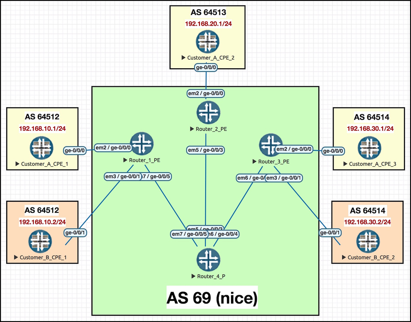
Hey, remember this? It’s the very same network as last time! The only difference is that instead of two interfaces between the hub PE and CE, we’ve now got just the one. All the spoke config remains exactly the same as last time, so we won’t be touching any of the spoke PEs or CPEs.
PROTIP: It’s a nightmare having to constantly scroll up to look at topologies. Click this pic and open it up in a new tab, so you can refer back to it as you read this post.
The interfaces that connect the ISP’s core routers together are IP addressed in the format 10.10.xy.z, where x y and z represent the router number. So for example, see interface ge-0/0/3 on Router 4? The interface that connects to Router 2? The IP address of this interface is 10.10.24.4. Do your best to remember that IP address in particular, and where it lives, because we’ll see it later on.
What are we trying to achieve here? We’ll have succeeded first when the hub CPE learns the individual LAN ranges of all the spokes sites – and second when the spoke sites learn a default route, and only a default route, which the hub site will have generated.
THE EASY WAY: ADDING CONFIG TO THE CUSTOMER’S HUB CPE
Let’s configure our customer’s CPE router. After all, they’re paying us lots of money (in my imagination).
First, let’s define the one single WAN interface on the customer CPE router:
edit interfaces ge-0/0/0 unit 0
set description "To ISP - Spoke BGP Prefixes In, Traffic Out"
set family inet address 10.10.250.101/31
Next I’ll configure a default route let’s add a default route.
Do you know what a “generate” route is in Junos? It’s a way of automatically creating an aggregate route, as long as there are “contributing routes” in the routing table. The contributing routes have to come from somewhere other than the box itself, so directly connected routes don’t count. Another way of saying it is like this: using the config below, we’ll only install a default route if we’re receiving prefixes by BGP. In this scenario, the next-hop will be PE2, which is exactly what we want.
set routing-options generate route 0.0.0.0/0
I’m going to skip ahead slightly, to show you what the result of this command is. Bear in mind that the output below is actually coming from the very end of this lab, when everything is complete. I’m just showing you this now to help you to visualise what that “generate” command will do. Notice that it’s created a default route, and that it mentions all the BGP prefixes as contributors. If the BGP goes down, the default route goes down. And that’s exactly what we want to happen!
root@CUSTOMER_A_CPE_2> show route 0/0 exact detail
inet.0: 9 destinations, 9 routes (9 active, 0 holddown, 0 hidden)
0.0.0.0/0 (1 entry, 1 announced)
        *Aggregate Preference: 130
                Next hop type: Router, Next hop index: 544
                Address: 0x934c400
                Next-hop reference count: 10
                Next hop: 10.10.250.100 via ge-0/0/0.0, selected
                State: <Active Int Ext>
                Local AS: 64513
                Age: 1:48:06
                Task: Aggregate
                Announcement bits (2): 0-KRT 2-BGP_RT_Background
                AS path: I
                                Flags: Generate Depth: 0 Active
                Contributing Routes (4):
                10.10.250.0/31 proto BGP
                10.10.250.6/31 proto BGP
                192.168.10.0/24 proto BGP
                192.168.30.0/24 proto BGP
Okay, back to our present time. We need to do one extra thing, because there’s a problem: the next-hop our CPE chooses for this generate default route is of course PE 2. The problem though is that CPE2 is advertising this default route to PE2, to re-advertise to the other sites. If PE 2 receives a route from CPE 2, and PE 2 sees that PE 2 itself is the next-hop for the route, PE 2 won’t accept it.
To fix this, notice that on the BGP peering below we’ve got a next-hop self policy. That’ll do the trick. Now when PE 2 receives the default route, it will see CPE 2 as the next-hop.
edit protocols bgp group TO_ISP
set type external
set peer-as 69
set neighbor 10.10.250.100
set description "TO ISP"
set export [ NEXT_HOP_SELF EXPORT_DEFAULT_ROUTE ]
You can imagine that this causes problems if your hub site genuinely needs a default route. If the hub CPE thinks it can get to everywhere via the hub PE, but the hub PE also sees that the CPE is advertising a default route with itself as the next-hop… well, that’s a good old fashioned routing loop! The two-interface approach might be better in that circumstance.
Anyway, here’s our two export policies on the CPE’s BGP peering. The first one exports the default route, the second one sets the next-hop self. You can see above in the BGP config that we chained them together. Note that even though we made a generate route, we redistribute from “protocol aggregate“. Aah, don’t you love vendor syntax?
policy-options {
    policy-statement EXPORT_DEFAULT_ROUTE {
        from {
            protocol aggregate;
            route-filter 0.0.0.0/0 exact;
        }
        then accept;
    }
    policy-statement NEXT_HOP_SELF {
        then {
            next-hop self;
}}}
THE EASY WAY: ADDING CONFIG tO THE ISP’s HUB PE ROUTER
Do you remember how in our two-interface examples we configured our spoke PE routers to export everything with a SPOKE target community attached, and to import only prefixes with the HUB target community attached? Well, in the one-interface-at-the-hub topology we do exactly the same thing again at the spokes. The config at the spokes in this topology is exactly the same as the config I showed you last week, in the two-interface post.
As for the hub, we actually use the exact same philosophy, but in reverse: we accept anything with the SPOKE target community, and then we advertise everything out with the HUB target community attached. Here’s the VRF config at the hub.
root@Router_2_PE> show configuration routing-instances
VRF_CUSTOMER_A_HUB {
    instance-type vrf;
    interface ge-0/0/0.0;
    route-distinguisher 2.2.2.2:1;
    vrf-import POLICY_CUSTOMER_A_SPOKES_ADVERTISING_TO_HUB;
    vrf-export POLICY_CUSTOMER_A_HUB_ADVERTISING_TO_SPOKES;
    protocols {
        bgp {
            group CUSTOMER_A_CPE_2 {
                type external;
                peer-as 64513;
                neighbor 10.10.250.101;
}}}}
There is one extra difference though, which is that in our hub-to-spoke policy I’ve explicitly mentioned to only accept the default route. This isn’t really necessary: I do it just for my own readability.
root@Router_2_PE> show configuration policy-options
policy-statement POLICY_CUSTOMER_A_HUB_ADVERTISING_TO_SPOKES {
    from {
        protocol bgp;
        route-filter 0.0.0.0/0 exact;
    }
    then {
        community add TARGET_COMMUNITY_CUSTOMER_A_HUB_ADVERTISING_TO_SPOKES;
        accept;
}}
policy-statement POLICY_CUSTOMER_A_SPOKES_ADVERTISING_TO_HUB {
    from community TARGET_COMMUNITY_CUSTOMER_A_SPOKES_ADVERTISING_TO_HUB;
    then accept;
}
community TARGET_COMMUNITY_CUSTOMER_A_HUB_ADVERTISING_TO_SPOKES members target:69:200;
community TARGET_COMMUNITY_CUSTOMER_A_SPOKES_ADVERTISING_TO_HUB members target:69:100;
Does it work? Let’s go over to Router PE 3, and see how PE 3 thinks it can get to the LAN of CPE 1:
root@Router_3_PE> show route table CUSTOMER_A.inet.0 192.168.10.0/24 best

CUSTOMER_A.inet.0: 4 destinations, 5 routes (4 active, 0 holddown, 0 hidden)
+ = Active Route, - = Last Active, * = Both

0.0.0.0/0          *[BGP/170] 00:22:08, localpref 100, from 4.4.4.4
                      AS path: 64513 I, validation-state: unverified
                    > to 10.10.34.4 via ge-0/0/4.0, Push 300256, Push 299808(top)
Nice! PE 3 is receiving the default route, which means it can get to everything via the hub.
And hey, let’s make sure it’s working as expected, by doing a traceroute from CPE 3 to CPE 1. Does traffic go via the hub CPE?
root@CUSTOMER_A_CPE_3> traceroute 192.168.10.1 no-resolve wait 1
traceroute to 192.168.10.1 (192.168.10.1), 30 hops max, 40 byte packets
1  10.10.250.6  9.195 ms  9.611 ms  10.109 ms       <--- PE 3's customer-facing interface
2  * * *                                            <--- P 4, which isn't VRF aware
3  10.10.24.2  15.121 ms  9.544 ms  14.767 ms       <--- PE 2's core-facing interface
     MPLS Label=300256 CoS=0 TTL=1 S=1
4  10.10.250.101  19.254 ms  19.624 ms  19.639 ms   <--- CPE 2's WAN interface
5  10.10.250.100  14.819 ms  14.653 ms  14.599 ms   <--- PE 2's customer-facing interface
6  * * *                                            <--- P 4 again, the cheeky monkey!
7  10.10.14.1  20.089 ms  19.689 ms  19.644 ms      <--- PE 1's core-facing interface
     MPLS Label=300288 CoS=0 TTL=1 S=1
8  192.168.10.1  34.253 ms  29.984 ms  29.552 ms    <--- CPE 1's LAN interface
Perfect. 🙂
LET’S THINK MORE ABOUT HOW THE ROUTING IS WORKING HERE
Let’s look at how the final routing table looks from the perspective of the hub PE. In particular, I want to look at the default route, and also the route to the LAN on CPE 1, 192.168.10.0/24. I’m going to take you on a journey that will hopefully show you how using vrf-table-label changes things here.
root@Router_2_PE> show route table VRF_CUSTOMER_A_HUB.inet.0

VRF_CUSTOMER_A_HUB.inet.0: 7 destinations, 7 routes (7 active, 0 holddown, 0 hidden)
+ = Active Route, - = Last Active, * = Both

0.0.0.0/0          *[BGP/170] 00:00:16, localpref 100
                      AS path: 64513 I, validation-state: unverified
                    > to 10.10.250.101 via ge-0/0/0.0
{snip}
192.168.10.0/24    *[BGP/170] 00:00:16, localpref 100, from 4.4.4.4
                      AS path: 64512 I, validation-state: unverified
                    > to 10.10.24.4 via ge-0/0/3.0, Push 299824, Push 299808(top)
{snip}
This routing table is very clear:
- If the traffic matches the default route, go via ge-0/0/0.0 – in other words, the link to the customer’s hub CPE.
- To get to spoke CPE 1’s LAN range, go there via the link to router P4, and push two MPLS labels on.
Now remember, the only route that PE 2 is advertising to the rest of the network is the default route. PE2 isn’t advertising the rest of the spoke LAN prefixes. Let’s look in detail at what PE2 is advertising to the route reflector:
root@Router_2_PE> show route advertising-protocol bgp 4.4.4.4 table VRF_CUSTOMER_A_HUB.inet.0 extensive

VRF_CUSTOMER_A_HUB.inet.0: 7 destinations, 7 routes (7 active, 0 holddown, 0 hidden)
* 0.0.0.0/0 (1 entry, 1 announced)
BGP group AS69 type Internal
     Route Distinguisher: 2.2.2.2:1
     VPN Label: 299936
     Nexthop: Self
     Flags: Nexthop Change
     Localpref: 100
     AS path: [69] 64513 I
     Communities: target:69:200
The VPN label is important. If the customer router CPE 3 wants to send traffic to the customer’s CPE 1, it does so by sending the traffic to the ISP’s PE 3, who then sends the traffic to PE 2, with VPN label 299936 attached to every packet. This means that when the traffic arrives at PE 2, it doesn’t look at the destination IP. PE 2 doesn’t care in the slightest that the packet is ultimately destined to CPE 1. PE 2 sees the label, and so sends it to the customer’s hub CPE.
This is the default behaviour, and it’s exactly what we want. We’re doing hub-and-spoke, after all.
Now imagine this same scenario with vrf-tabel-label configured on the VRF at the hub. Once again traffic goes from CPE 3 to PE 3, who adds VPN label 299936, and sends it to PE 2. This time however, PE 2 strips the VPN label, and actually looks at the destination IP address. PE 2 sees that the destination is 192.168.10.1… and do you remember how PE 2 itself gets to CPE 1, when it does a lookup on that IP address?
root@Router_2_PE> show route table VRF_CUSTOMER_A_HUB.inet.0 192.168.10.1

VRF_CUSTOMER_A_HUB.inet.0: 7 destinations, 7 routes (7 active, 0 holddown, 0 hidden)
+ = Active Route, - = Last Active, * = Both

192.168.10.0/24    *[BGP/170] 00:08:56, localpref 100, from 4.4.4.4
                      AS path: 64512 I, validation-state: unverified
                    > to 10.10.24.4 via ge-0/0/3.0, Push 299824, Push 299808(top)
That’s right – it goes directly to PE 1, NOT via the hub! There’s that 10.10.24.4 IP address. Did you remember it like I told you to? Give yourself a pat on the back if you did. Remember to stretch before you pat yourself though, I don’t want you pulling a muscle. Junos is cool, but it’s not worth injuring yourself for it.
So, if you’re running vrf-table-label, it’s clear that we need to do something a little extra to get around this. What we really need is a way for the PE router to look at the default route, and only the default route, so that traffic goes to the hub regardless of its destination. But how on earth can we achieve that that?
Well, one way could involve policy-based routing, where you route based on the source rather than the destination. But that’s very complicated, and there’s a much easier way. What is it? Read on, friend. Your life may well depend on it one day*…..
(*Note: your life almost certainly won’t depend on it one day.)
THE HARDER WAY – THE CONFIG ON THE HUB CPE
Good news: the config on the CPE is exactly the same!
Bad news: there’s lots to do on the hub PE.
THE HARDER WAY – THE CONFIG ON THE HUB PE
Here’s our VRF config again – but this time, you’ll see a couple of new lines, which I’ve highlighted in red. Give the config a read, and then I’ll explain what these new bits do.
root@Router_2_PE> show configuration routing-instances VRF_CUSTOMER_A_SPOKES_ADVERTISING_TO_HUB
instance-type vrf;
interface ge-0/0/0.0;
route-distinguisher 2.2.2.2:1;
vrf-import POLICY_CUSTOMER_A_SPOKES_ADVERTISING_TO_HUB;
vrf-export POLICY_CUSTOMER_A_HUB_ADVERTISING_TO_SPOKES;
no-vrf-advertise;
vrf-table-label;
routing-options {
    auto-export;
}
protocols {
    bgp {
        group CUSTOMER_A_CPE_2 {
            type external;
            peer-as 64513;
            neighbor 10.10.250.101;
}}}
Once again, we’ve got a vrf-export policy. However, in this VRF you can also see the command “no-vrf-advertise“. Hmm. Does that command do what it says on the tin, and stop prefixes from being advertised out to the other PE routers? Well, indeed it does! That’s exactly what’s happening here. This VRF isn’t advertising anything out: it’s only accepting things in. So, err…. what’s the point in the vrf-export policy then?
FUNNY YOU SHOULD ASK.
Do you see the other command in here, the routing-options auto-export command? This is a real neat feature. Here’s the concept: imagine you had two VRFs on the same PE router, and you wanted to leak routes between them: exporting prefixes from one VRF with one target community attached, and import those prefixes into the other VRF, with the same community attached.
Well, BAD NEWS: By default, these two VRFs wouldn’t actually learn about each other’s prefixes. Why? Because the target communities only get added on at the point that the prefixes are advertised out to other PE routers, by BGP. If a route is learned from a CPE, it’ll be in the local PE router’s routing table, but the target community isn’t added on. As such, the export policy won’t work, because the target communities haven’t been added on.
The auto-export command changes this behaviour. If you add the command into a VRF, then prefixes from a VRF are indeed eligible to be leaked to other VRFs on the local box.
…Do you see where this is going?
The solution when you’re running vrf-table-label is to define a second VRF, just like we did in the two-interface scenario. Then, instead of advertising the default route out of the first VRF, like we did in the “easy” method, what we’ll do is export the default route from the first VRF to the second VRF, which will give us a new VRF with just one single route in it: the default route, pointing to the hub CPE.
This is why we have the “no-vrf-advertise” command on the first VRF. We’re not going to advertise the default route out of the VRF. Instead we’re exporting it to the second VRF, and advertising it from there. Which means that when the hub PE receives a packet, strips the VPN label, and does the IP routing lookup, it sees one and only one route: the default route.
Wow, what a concept!
Here’s the config for our second VRF. It’s quite short and simple, really. Notice that there’s no interfaces in this VRF, even though the traffic is ultimately going out of an interface. The route leaking take care of that, as we’ll see in a moment.
root@Router_2_PE> show configuration routing-instances VRF_CUSTOMER_A_HUB_ADVERTISING_TO_SPOKES
instance-type vrf;
route-distinguisher 2.2.2.2:2;
vrf-target target:69:200;
routing-options {
    auto-export;
}
Did it work? Let’s look at the routing table for this new VRF:
root@Router_2_PE> show route table VRF_CUSTOMER_A_HUB_ADVERTISING_TO_SPOKES

VRF_CUSTOMER_A_HUB_ADVERTISING_TO_SPOKES.inet.0: 1 destinations, 1 routes (1 active, 0 holddown, 0 hidden)
+ = Active Route, - = Last Active, * = Both

0.0.0.0/0          *[BGP/170] 00:00:06, localpref 100
                      AS path: 64513 I, validation-state: unverified
                    > to 10.10.250.101 via ge-0/0/0.0
So far so good! The next-hop for this default route is correctly pointing out of the customer-facing interface, to CPE 2.
Time for the final test: let’s once again do a traceroute, to see if traffic is going via the hub CPE:
root@CUSTOMER_A_CPE_3> traceroute 192.168.10.1 no-resolve wait 1
traceroute to 192.168.10.1 (192.168.10.1), 30 hops max, 40 byte packets
1  10.10.250.6  6.667 ms  9.763 ms  9.650 ms
2  * * *
3  10.10.24.2  14.856 ms  9.572 ms  9.809 ms
     MPLS Label=299952 CoS=0 TTL=1 S=1
4  10.10.250.101  23.785 ms  19.696 ms  14.952 ms
5  10.10.250.100  14.466 ms  9.914 ms  14.492 ms
6  * * *
7  10.10.14.1  24.867 ms  19.792 ms  19.544 ms
     MPLS Label=299824 CoS=0 TTL=1 S=1
8  192.168.10.1  29.445 ms  29.364 ms  24.671 ms
Perfect. 🙂
THAT’S IT!
If you’re not running vrf-table-label, I can see why Juniper would recommend the one-interface approach: it’s surprisingly simple. One community in, another community out. Bada-bing, bada-boom!
If you ARE running vrf-table-label, I’d argue that the two-interface approach is easier to understand, even if it does involve more configuration. The auto-export command isn’t a very well-known feature, which potentially makes it harder for junior engineers to understand what’s going on. Which of course isn’t a reason in itself not to use it, but I do think it’s good to favour simplicity whenever possible. Of course, you will have your own opinion – and let me reassure you that if you disagree with me, there is absolutely no need to tell me.
Click here to read the third part in this series, where we return to the two-interface approach, and add in a ton of extra tweaks to see all the weird and wonderful way that this topology can break in the real world. And of course, we’ll see how to fix it.
In the mean time, please do share this post on your social media of choice if you enjoyed it! The more people share my posts, the bigger my reach, and the bigger my smile. 🙂 Share it far and wide, and help me to get more readers!
If you’re on Mastodon, follow me to find out when I make new posts. (2024 edit: I’m also on BlueSky nowadays too. I was once on Twitter, but I’ve given up on it, on account of… well, I don’t need to finish that sentence, do I.)
And if you fancy some more learning, take a look through my other posts. I’ve got plenty of cool new networking knowledge for you on this website, especially covering Juniper tech and service provider goodness.
It’s all free for you, although I’ll never say no to a donation. This website is 100% a non-profit endeavour, in fact it costs me money to run. I don’t mind that one bit, but it would be cool if I could break even on the web hosting, and the licenses I buy to bring you this sweet sweet content.