

HUB-AND-SPOKE MPLS L3VPNs WITH TWO INTERFACES, ON JUNIPER JUNOS ROUTERS
“The Network Fun-Times First Rule Of Networking” goes as follows: “If it’s possible to build a network in a certain way, then at least one person will have, even if they shouldn’t have.”
For that reason, it’s incumbent on us network engineers at all times to know literally every single thing there is to know about every protocol that’s ever been made ever, even protocols that haven’t been used for over 750 years, and to know how they’ll behave even in designs that no-one would ever dream of deploying in real life – because one day, in the future, this knowledge means we’ll be able to resolve a ticket 5 minutes quicker than we could have if we’d just Googled it. Great! I’m very happy with my life choices.
Hub-and-spoke MPLS L3VPNs feel a bit like that to me. I’ve personally never seen one in production, at least not in the way they’re documented by the vendors, and having talked with colleagues in the industry, this solution seem very rare indeed. But, it’s precisely because they’re rare that it’s all the more important that we make sure we’re fully aware of all the moving parts, and the inevitable gotchas that come along with this more complicated topology.
And do you know what? If networking is a hobby for you, if it’s a true interest, then actually these odd corner-cases can only serve to deepen your knowledge of the protocols. Seeing the way the various elements interact, and the challenges that come along with it, help to make you a next-level engineer. That’s why, even though these topologies are rare, I was excited to try to master them.
~.~.~.~.~.~.~.~.~.~.~.~.~
In today post we’ll be exploring how you can set up hub-and-spoke MPLS L3VPNs on Juniper routers. I’ll show you the extra steps you need to deploy them as opposed to the regular full-mesh kind. In particular, in this post we’ll be using the “two logical interfaces” approach at the customer’s premises – one WAN sub-interface to take BGP advertisements in, and one WAN sub-interface to re-advertise the BGP prefixes back out again.
Then, next week in a follow-up post we’ll see how things work differently when you just have one single sub-interface between PE and customer router. And finally, after all of that, in part 3 we’ll see how certain design choices can lead to extra problems, such as using the same AS number at all of your sites, or using independent-domain within the ISP.
For now though, let’s get the basics down. Grab your popcorn, and prepare yourself to have the MOST FUN YOU’VE EVER HAD IN YOUR ENTIRE LIFE, as we learn a cool new thing!
A QUICK REFRESH ON FULL-MESH MPLS L3VPNs
(You can skip this section if you’re comfortable with the concept already)
You probably already know that a key part of a layer 3 MPLS VPN is the route-target. This is an extended community, added on to the BGP advertisements between PEs (Provider Edge routers), which tells the receiving PE router which VRF the prefix is a part of. So for example, in the config below:
routing-instances {
    CUSTOMER_BARRYS_BEEFCAKE_EMPORIUM {
        instance-type vrf;
        interface ge-0/0/0.0;
        route-distinguisher 1.1.1.1:1;
        vrf-target target:64512:420
}}
…we’re telling our PE router to import any prefixes into the VRF that have the route-target “target:64512:420” attached to it. Almost everyone uses the first number (64512) as their autonomous system number, and the second number (420) as just a unique number in the network. Why 420 in this example? No reason. No reason at all.
In the config above we’re also telling our PE router to attach this target to any prefixes it advertises out to the other PEs in our ISP’s network, so that the other PEs can do the same thing.
An alternative to using the vrf-target command is to write a policy that imports/exports a number of route-targets, depending on what IP range the prefix is in. It’s this policy-based approach that we use to create hub-and-spoke MPLS L3VPNs – because in hub and spoke, we don’t actually import and export the same community! Curious? Then read on. (Not curious? That’s okay too. Your life is yours to live however you like.)
OUR TOPOLOGY
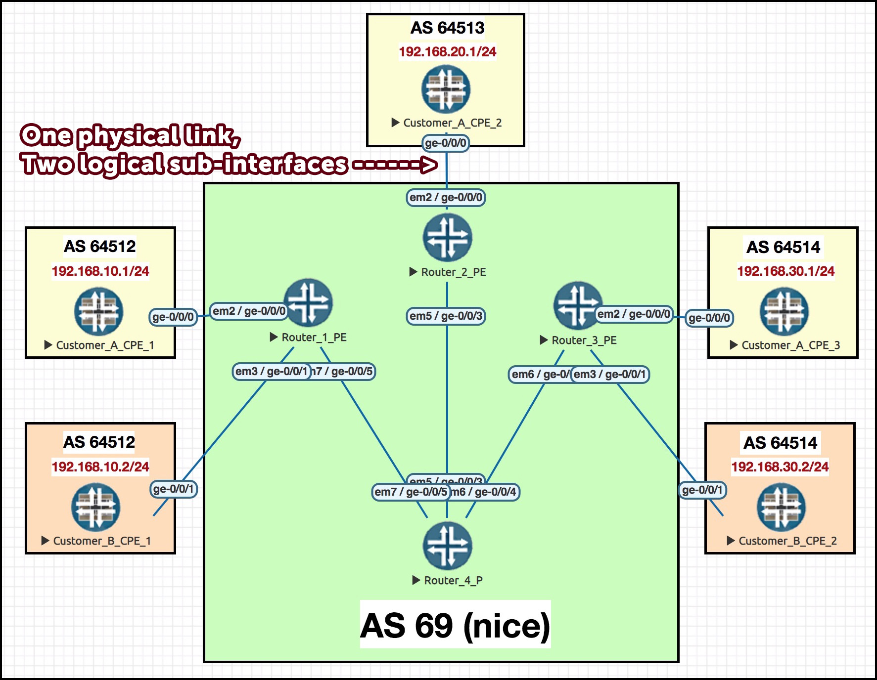
Here’s our network for today. Isn’t it handsome!
We’ve got two VPN customers, here, customer A and B. Notice that some of Customer A’s sites are using the same private IP space as Customer B for their LANs. The 4,000,000 IQ move that I use in labs is to give all the LAN interfaces for Customer A an IP address ending x.x.x.1, and to set all the LAN interfaces for Customer B to end in x.x.x.2. This allows me to ping around the place, and know for certain whether I’m correctly pinging Customer A, or incorrectly pinging Customer B. Pretty clever if you ask me, the person who thought of it.
You can see that we have three PE routers, with two spoke sites (hosted by PEs R1 and R3) and one hub site (hosted by PE R2).
Our ISP is, inevitably, AS number 69. Nice.
HOW SHOULD THE TRAFFIC FLOW?
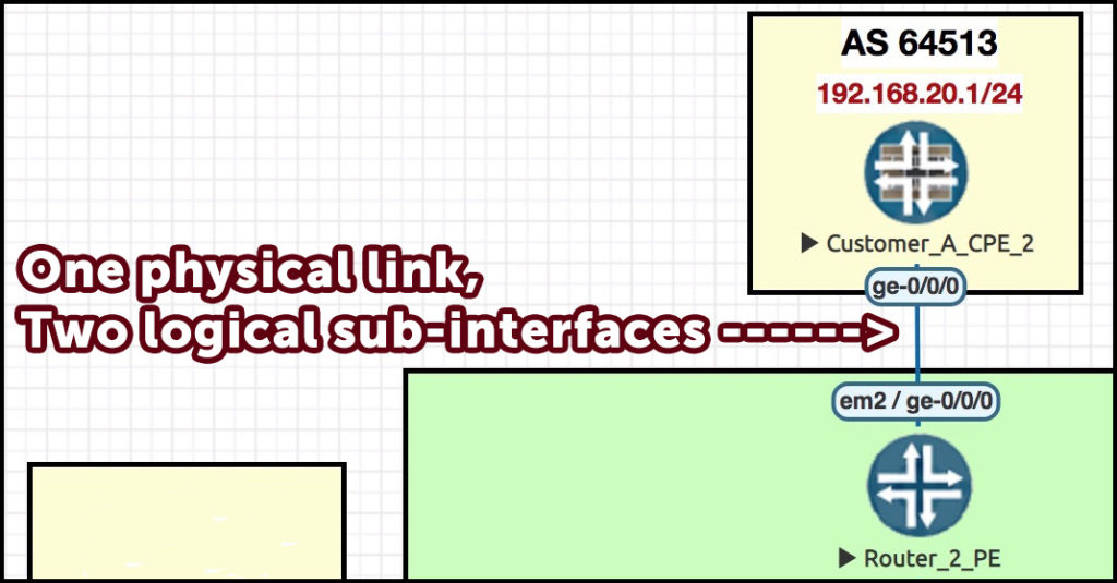 At the PE-to-CPE (Customer Premises Equipment) hub, the WAN interface ge-0/0/0 has been sub-interfaced twice.
Here’s what’s going to happen: the PE’s ge-0/0/0.10 is going to take BGP prefixes in from the rest of the MPLS network, and advertise them to the hub CPE .
By contrast, the CPE’s ge-0/0/0.20 is going to do the opposite: learn prefixes FROM the hub CPE, and advertise them TO the rest of the MPLS network.
If that’s the direction that the BGP advertisements are going, then it means our actual customer traffic will of course go the opposite way: destined from the PE to the hub CPE on ge-0/0/0.20, because it’s this CPE interface that’s telling the PE to come this way to get to stuff.
Similarly, ge-0/0/0.10 is the CPE interface the traffic will go out of, once it’s gone via the hub.
In our lab, every CPE is going to talk BGP to their PE. We’ve put each CPE into its own unique private AS, to avoid any complexity that comes with customer AS-PATH loops.
We’ll have succeed when a ping from CPE 3 to CPE 1 goes like this:
- From Customer_A_CPE_3 to Router_3_PE
- From Router_3_PE to Router_4_P, and then to Router_2_PE
- Out of Router_2_PE’s ge-0/0/0.20 interface, and in to CPE_2’s ge-0/0/0.20 interface
- Out of CPE_2’s ge-0/0/0.10 interface, and in to Router_2_PEs ge-0/0/0.10 interface
- From Router_2_PE to Router_4_P, to Router_1_PE
- And finally, from Router_1_PE to the destination, Customer_A_CPE_1.
“But wait: that’s a stupid path to take when it could just go directly to the destination”. Yep! That’s the magic of hub-and-spoke, baby!!!!
One final thing: I’m deliberately going to miss out a few important bits of config as we go along, so I can show you what it looks like when you do it wrong, before we then go ahead and fix it. See if you can spot the bits we’re missing as we configure it!
STEP 1: CONFIG ON THE SPOKE PEs
On every single PE router we’re going to define two target communities, which we’ll name as follows:
- TARGET_COMMUNITY_CUSTOMER_A_HUB_ADVERTISING_TO_SPOKE
- TARGET_COMMUNITY_CUSTOMER_A_SPOKE_ADVERTISING_TO_HUB.
A long name, that tells us exactly what it’s doing. You may choose to use shorter names in your lab or in production, in which case, good luck remembering the direction that everything goes in. I wish you all the best in your short-name adventures.
As you might guess from the names I’m using, when our spoke PEs advertises prefixes out of this VRF to the other PEs, our source PE will attach the spoke-advertising-to-hub community to the prefix.
But, crucially, our spokes are not going to accept any prefixes into this VRF from other spokes. Instead, we’re going to import only the prefixes the hub advertises. Can you guess which of the two communities that’s going to be? If you can’t, maybe it’s time to take a break. You’ve clearly been awake for far too long. Maybe have a nap?
The config on the spokes is much like anything you’ve seen before. This output is from R1. Here’s the communities, and the routing-instance:
policy-options {
    community TARGET_COMMUNITY_CUSTOMER_A_HUB_ADVERTISING_TO_SPOKE members target:69:200;
    community TARGET_COMMUNITY_CUSTOMER_A_SPOKE_ADVERTISING_TO_HUB members target:69:100;
}
routing-instances {
    CUSTOMER_A {
        instance-type vrf;
        interface ge-0/0/0.0;
        route-distinguisher 1.1.1.1:1;
        vrf-import CUSTOMER_A_IMPORT;
        vrf-export CUSTOMER_A_EXPORT;
        protocols {
            bgp {
                group CUSTOMER_A_CPE_1 {
                    type external;
                    peer-as 64512;
                    neighbor 10.10.250.1;
}}}}}
The main difference here with this setup is that unlike a full-mesh MPLS L3VPN, we’re importing and exporting different communities. Let’s see what the policies actually looks like. Notice that the CUSTOMER_A_EXPORT policy matches everything, and therefore attaches the spoke-to-hub community to all prefixes it advertises – because when there’s no “from” condition, a routing policy matches everything.
policy-options {
    policy-statement CUSTOMER_A_EXPORT {
        term 1 {
            then {
                community add TARGET_COMMUNITY_CUSTOMER_A_SPOKE_ADVERTISING_TO_HUB;
                accept;
            }
        }
    }
    policy-statement CUSTOMER_A_IMPORT {
        term 1 {
            from community TARGET_COMMUNITY_CUSTOMER_A_HUB_ADVERTISING_TO_SPOKE;
            then accept;
        }
        term 2 {
            then reject;
}}}
STEP 2: CONFIG ON THE HUB PE
Here’s the PE-to-CE pic again, to save you from scrolling up. You’re very busy, after all. Too busy for all this scrolling back and forth. Let me do the work for you. Just remember to leave me a generous tip at the end, okay? Okay.
First, the simple bit. At the hub PE, Router 2, let’s split our WAN link into two logical sub-interfaces, each with its own VLAN tag to distinguish the traffic.
We talked before about how one interface was for inbound traffic, and one for outbound. But there’s something I’ve not told you yet: in a moment we’re going to define TWO VRFs – one for each sub-interface. Crikey!
interfaces {
    ge-0/0/0 {
        vlan-tagging;
        unit 10 {
            description "CUSTOMER - To CUSTOMER_A_CPE_2 - Spoke BGP Prefixes In, Traffic Out";
            vlan-id 10;
            family inet {
                address 10.10.250.100/31;
            }
        }
        unit 20 {
            description "CUSTOMER - To CUSTOMER_A_CPE_2 - Hub BGP Prefixes Out, Traffic In";
            vlan-id 20;
            family inet {
                address 10.10.250.102/31;
}}}}
Ooh, it’s so tasty I could almost eat it! (Warning: do not eat Juniper routers. They are made of metal, and taste like routers, which taste bad.)
We now need to make two VRFs on PE2, for this one customer. Here’s the concept: one VRF is going to be for traffic from the spokes to the hub, and the other VRF is going to be for traffic from the hub back to the spokes.
Let’s first look at the VRF that imports the TARGET_COMMUNITY_CUSTOMER_A_SPOKE_ADVERTISING_TO_HUB community. Pay close attention to the policies. You can see that we’re importing all advertisements from all spokes – but we’re advertising NOTHING out! This is exactly what we want: the BGP advertisements are a one-way street. They come in on this VRF, and out of the other one.
routing-instances {
    VRF_CUSTOMER_A_SPOKES_ADVERTISING_TO_HUB {
        instance-type vrf;
        interface ge-0/0/0.10;
        route-distinguisher 2.2.2.2:1;
        vrf-import POLICY_CUSTOMER_A_SPOKES_ADVERTISING_TO_HUB;
        vrf-export POLICY_NOTHING_EXPORTED;
        protocols {
            bgp {
                group CUSTOMER_A_CPE_2 {
                    type external;
                    peer-as 64513;
                    neighbor 10.10.250.101;
}}}}}
Here’s the two policies.
policy-options {
    policy-statement POLICY_CUSTOMER_A_SPOKES_ADVERTISING_TO_HUB {
        from community TARGET_COMMUNITY_CUSTOMER_A_SPOKES_ADVERTISING_TO_HUB;
        then accept;
    }
    policy-statement POLICY_NOTHING_EXPORTED {
        then reject;
    }
}
At this point, the customer’s spoke routers CPE1 and CPE3 are fully set up, and BGP is working between the CPE and the PE routers. Which means that if this policy works, our HUB PE2 should see some prefixes in its VRF_CUSTOMER_A_SPOKES_ADVERTISING_TO_HUB VRF. Let’s see:
root@Router_2_PE> show route table VRF_CUSTOMER_A_SPOKES_ADVERTISING_TO_HUB.inet.0

VRF_CUSTOMER_A_SPOKES_ADVERTISING_TO_HUB.inet.0: 6 destinations, 10 routes (6 active, 0 holddown, 4 hidden)
+ = Active Route, - = Last Active, * = Both

{snip}
192.168.10.0/24    *[BGP/170] 01:52:06, localpref 100, from 4.4.4.4
                      AS path: 64512 I, validation-state: unverified
                    > to 10.10.24.4 via ge-0/0/3.0, Push 299824, Push 299808(top)
192.168.30.0/24    *[BGP/170] 01:52:07, localpref 100, from 4.4.4.4
                      AS path: 64514 I, validation-state: unverified
                    > to 10.10.24.4 via ge-0/0/3.0, Push 299824, Push 299792(top)
Cool! We know for sure that this piece is working now: we’re receiving prefixes, and putting them into the correct VRF.
While we’re still on PE2, let’s configure the other VRF as well. We’ll call it VRF_CUSTOMER_A_HUB_ADVERTISING_TO_SPOKES. This one does the exact opposite: it advertises to the spokes all the prefixes it learns from the hub CPE. This VRF imports nothing at all.
routing-instances {
    VRF_CUSTOMER_A_HUB_ADVERTISING_TO_SPOKES {
        instance-type vrf;
        interface ge-0/0/0.20;
        route-distinguisher 2.2.2.2:2;
        vrf-import POLICY_NOTHING_IMPORTED;
        vrf-export POLICY_CUSTOMER_A_HUB_ADVERTISING_TO_SPOKES;
        protocols {
            bgp {
                group CUSTOMER_A_CPE_2 {
                    type external;
                    peer-as 64513;
                    neighbor 10.10.250.103;
}}}}}
You wanna see the policies? Course you do!
policy-options {
    policy-statement POLICY_CUSTOMER_A_HUB_ADVERTISING_TO_SPOKES {
        then {
            community add TARGET_COMMUNITY_CUSTOMER_A_HUB_ADVERTISING_TO_SPOKES;
            accept;
        }
    }
   policy-statement POLICY_NOTHING_IMPORTED {
        then reject;
}}
SETTING UP THE CUSTOMER HUB ROUTER
Here’s the interesting config on the customer’s CPE hub router. It’s very similar to a typical customer CPE – the differences being that there’s multiple WAN sub-interfaces, and two peerings to the same ISP. Let’s sub-interface our WAN here too, and also configure a LAN:
interfaces {
    ge-0/0/0 {
        vlan-tagging;
        unit 10 {
            description "To ISP - Spoke BGP Prefixes In, Traffic Out";
            vlan-id 10;
            family inet {
                address 10.10.250.101/31;
            }}
        unit 20 {
            description "To ISP - Hub BGP Prefixes Out, Traffic In";
            vlan-id 20;
            family inet {
                address 10.10.250.103/31;
            }}}
    ge-0/0/1 {
        unit 0 {
            description LAN;
            family inet {
                address 192.168.20.1/24;
            }}}}
Next, the BGP to peer with the ISP. Two peerings, one out of each sub-interface.
protocols {
    bgp {
        group TO_ISP_SPOKE_PREFIXES_IN {
            type external;
            peer-as 69;
            neighbor 10.10.250.100;
        }
        group TO_ISP_HUB_AND_SPOKE_PREFIXES_OUT {
            type external;
            export EXPORT_CONNECTED;
            peer-as 69;
            neighbor 10.10.250.102;
}}}

policy-options {
    policy-statement EXPORT_CONNECTED {
        from protocol direct;
        then accept;
}}
TESTING THE HUB CPE’s BGP ADVERTISEMENTS
So, let’s see if it’s working. First, is our hub CPE learning prefixes from the ISP via the correct peering – the ge-0/0/0.10 interface?
root@CUSTOMER_A_CPE_2> show route receive-protocol bgp 10.10.250.100 terse

inet.0: 10 destinations, 10 routes (10 active, 0 holddown, 0 hidden)

  Prefix   Nexthop       MED     Lclpref    AS path
* 10.10.250.0/31          10.10.250.100                           69 I
* 10.10.250.6/31          10.10.250.100                           69 I
* 192.168.10.0/24         10.10.250.100                           69 64512 I
* 192.168.30.0/24         10.10.250.100                           69 64514 I
We sure are! So far, so “good”. Now, let’s see if these prefixes are being advertised back out the ge-0/0/0.20 interface:
root@CUSTOMER_A_CPE_2> show route advertising-protocol bgp 10.10.250.102

inet.0: 10 destinations, 10 routes (10 active, 0 holddown, 0 hidden)

  Prefix   Nexthop       MED     Lclpref    AS path

* 10.10.250.100/31        Self                                    I
* 10.10.250.102/31        Self                                    I
* 192.168.20.0/24         Self                                    I
Hmm. Hmmmm! How strange: we’re successfully advertising our directly-connect ranges – but we’re not re-advertising what we learnt by BGP. We should be re-advertising them, right? Why isn’t this working? Let’s have a think about this one.
Perhaps it’s the export policy? After all, it only mentions exporting directly connected routes. Should we edit our policy to explicitly mention exporting routes learnt by BGP? Well, you might remember that “accepting all BGP routes” is actually the default policy on BGP, so we don’t need to explicitly refer to it in our policy.
Is there a loop in AS69? Well, yes, and you’re getting warmer – but that’s not quite the reason either. The loop detection is for the receiving peer to worry about, not the sender. So, what is it?
Well, it turns out there’s actually a Juniper-specific behaviour at play here.
Imagine a Junos router has two separate BGP peerings, and both those peerings go to the same AS (you know: just like in this scenario!). If the Junos router learns about a prefix from its first peering to that AS, our Juniper friend won’t then advertise that prefix down the second peering to the same AS. The router decides that the other peer won’t want us advertising their own AS’s prefixes back to them.
Cisco doesn’t do this (as this blog post explains): Cisco routers will happily advertise prefixes to the second peer in the same AS. Now, you will have your own opinions on which vendor has the “better” default behaviour. In my opinion, neither behaviour is right or wrong: every situation is different, and the key is to know what the default behaviour is, and how to override it.
In this case, we can fix it with the addition of one simple command on the hub CPE:
set protocols bgp advertise-peer-as
When we add this, we suddenly see our beautiful prefixes being advertised out!
root@CUSTOMER_A_CPE_2> show route advertising-protocol bgp 10.10.250.102

inet.0: 10 destinations, 10 routes (10 active, 0 holddown, 0 hidden)

  Prefix   Nexthop       MED     Lclpref    AS path
* 10.10.250.0/31          Self                                    69 I
* 10.10.250.6/31          Self                                    69 I
* 10.10.250.100/31        Self                                    I
* 10.10.250.102/31        Self                                    I
* 192.168.10.0/24         Self                                    69 64512 I
* 192.168.20.0/24         Self                                    I
* 192.168.30.0/24         Self                                    69 64514 I
Cool! So we’re taking prefixes from AS69 (nice)… and advertising them back to AS69 (nice)… Wait a second… Can you see a potential problem here?
Let’s check back on PE2, and see if the routes are being received successfully:
root@Router_2_PE> show route receive-protocol bgp 10.10.250.103 table VRF_CUSTOMER_A_HUB_ADVERTISING_TO_SPOKES.inet.0

VRF_CUSTOMER_A_HUB_ADVERTISING_TO_SPOKES.inet.0: 4 destinations, 5 routes (4 active, 0 holddown, 0 hidden)

  Prefix   Nexthop       MED     Lclpref    AS path
* 10.10.250.100/31        10.10.250.103                           64513 I
  10.10.250.102/31        10.10.250.103                           64513 I
* 192.168.20.0/24         10.10.250.103                           64513 I
Nope! We’re receiving CPE2’s LAN range, but that’s it. Looks like we’ve got ourselves a good old fashioned routing loop, just like American cowboys used to battle on horseback in the olden days.
No worries though – because on our four ISP core routers there’s just one command we need to add around the place to allow this to work:
set routing-options loops 2
Has that fixed it? Let’s type “clear bgp neighbor 10.10.250.103 soft-inbound” to get our peer to re-advertise the prefixes, and then let’s see the result:
root@Router_2_PE> show route receive-protocol bgp 10.10.250.103 table VRF_CUSTOMER_A_HUB_ADVERTISING_TO_SPOKES.inet.0

VRF_CUSTOMER_A_HUB_ADVERTISING_TO_SPOKES.inet.0: 8 destinations, 9 routes (8 active, 0 holddown, 0 hidden)

  Prefix   Nexthop       MED     Lclpref    AS path
{snip}
* 192.168.10.0/24         10.10.250.103                           64513 69 64512 I
* 192.168.20.0/24         10.10.250.103                           64513 I
* 192.168.30.0/24         10.10.250.103                           64513 69 64514 I
Success! And what about our other PE routers around the place. Are they learning these prefixes too? Let’s see if PE3 is now learning the LAN of CPE 1:
root@Router_3_PE> show route table CUSTOMER_A.inet.0 192.168.10.0/24

CUSTOMER_A.inet.0: 8 destinations, 11 routes (8 active, 0 holddown, 0 hidden)
+ = Active Route, - = Last Active, * = Both

192.168.10.0/24    *[BGP/170] 00:04:17, localpref 100, from 4.4.4.4
                      AS path: 64513 69 64512 I, validation-state: unverified
                    > to 10.10.34.4 via ge-0/0/4.0, Push 299872, Push 299776(top)
Don’t you just love a happy ending?
TESTING THAT TRAFFIC IS FLOWING CORRECTLY
So, how to test? We could do a traceroute, but, I don’t know about you, but whenever I read other people’s blogs and they do a traceroute at the end to prove the scenario works, I rarely take the time to compare the IPs to the actual flow. I just trust the author when they say it works, because why would they publish a lie? Also, you’ve seen a thousand traceroutes in your life. You don’t need another.
So instead, let’s test it like this. First, we clear the counters on Router_2_PE’s ge-0/0/0 interface – the physical interface on the ISP side that hosts our two sub-interfaces. Then we check the state of the input and output counters before we do our test.
root@Router_2_PE> clear interfaces statistics ge-0/0/0

root@Router_2_PE> show interfaces ge-0/0/0 detail | match "ge-0/0/0|bytes"
{snip}
  Logical interface ge-0/0/0.10 (Index 338) (SNMP ifIndex 528) (Generation 161)
     Input  bytes  :                  175
     Output bytes  :                  248
{snip}
  Logical interface ge-0/0/0.20 (Index 339) (SNMP ifIndex 529) (Generation 162)
     Input  bytes  :                  246
     Output bytes  :                  318
{snip}
(Even after clearing the interface there’s still a little bit of traffic in both directions, because of BGP.)
Then we do a great big long huge massive ping from CPE 3 to CPE 1:
root@CUSTOMER_A_CPE_3> ping 192.168.10.1 source 192.168.30.1 rapid size 1500 count 1000000000
PING 192.168.10.1 (192.168.10.1): 1500 data bytes
!!!!!!!!!!!!!!!!!!!!!!!!!!!!!!!!!!!!!!!!!!!!!!!!!!!!!!!!!!!!!!!!!!!!!!!!!!!!!!!!
{snip}
Then, after a while, we check back in. I stopped the ping after a while, because the results were clear:
root@Router_2_PE> show interfaces ge-0/0/0 detail | match "ge-0/0/0|bytes"
{snip}
  Logical interface ge-0/0/0.10 (Index 338) (SNMP ifIndex 528) (Generation 161)
     Input  bytes  :             21823856
     Output bytes  :                 1609
{snip}
  Logical interface ge-0/0/0.20 (Index 339) (SNMP ifIndex 529) (Generation 162)
     Input  bytes  :                 1230
     Output bytes  :             21824254
{snip}
Look at that: we can see tons of traffic coming in to ge-0/0/0.10, and loads coming out of ge-0.0.0/20. That’s exactly what we wanted! It’s like a birthday and a Christmas, all rolled into one.
DOWNLOAD THE FULL TOPOLOGY CONFIG HERE
As always, you can click here to get the full config for all routers in this topology. I’m using vSRX for the CPEs and vMX in my ISP core, but you can easily adapt the config to whatever boxes you’re running.
THAT’S IT – UNTIL NEXT TIME!
And if you’re thirsty for more, that time is now! Click here to read Part 2, where we learn how to achieve the same thing using only one interface. There’s some restrictions to be aware of, but in a way it’s actually a little bit nicer. Give it a read to find out why!
But wait: how will you know when I make other cool posts teaching you fun neat new stuff? Don’t worry: I always share my blog posts on social media. If you’re on Mastodon, follow me to find out when I make new posts. (2024 edit: I’m also on BlueSky nowadays too. I was once on Twitter, but I’ve given up on it, on account of… well, I don’t need to finish that sentence, do I.)
And if you fancy some more learning, take a look through my other posts. I’ve got plenty of cool new networking knowledge for you on this website, especially covering Juniper tech and service provider goodness.
It’s all free for you, although I’ll never say no to a donation. This website is 100% a non-profit endeavour, in fact it costs me money to run. I don’t mind that one bit, but it would be cool if I could break even on the web hosting, and the licenses I buy to bring you this sweet sweet content.