

MAXIMISE YOUR JUNOS NETWORK WITH MPLS, PART 2: AUTO-BANDWIDTH
I once phoned up the council to try to reserve 50 miles an hour of bandwidth on the local motorway. “I need it”, I said. “I need it to guarantee I can get to the cinema on Saturday in time to watch their important Sharknado retrospective. David Hasselhoff is fabulous as Gilbert Grayson Shepard. You need to make this happen.”
I’m sad, and furious, to say that the council said no. “What you are asking for doesn’t make sense”, they said. “Stop wasting our time.” Anyway, long story short, I ended up becoming the local mayor, and I had the entire council put in jail for crimes against movies.
How does that relate to our blog post today? Good question. Much like my attempts to reserve bandwidth on the motorway, today’s post is Part 2 in our ongoing series about MPLS RSVP bandwidth reservations. Yes! Excellent introduction, very happy with that.
If you’ve not read Part 1 already then I’d highly recommend starting there. Based on the knowledge we learned in that post, today we’ll be exploring a concept that Juniper calls “auto-bandwidth”. We’re going to fully automate the management of bandwidth in our network, and let our lovely Juniper routers take care of getting the most out of all our links. It’s seriously cool, and I think you’re really going to enjoy learning about it.
Grab your snacks, re-adjust your underwear, and “get comfortable” with me, as we have yet more fun with MPLS!
WARNING: In my lab, almost every single piece of configuration in this post actually tore down existing LSPs, and re-created them. In other words, doing this caused a brief outage. Even just turning on the logging caused the LSP to flap. Make sure you extensively lab everything in this post yourself, before you deploy it into production, so that you know what impact this config will have on your own network.
SOME QUICK REVISION ON RSVP BANDWIDTH RESERVATION
In Part 1 we learned that an MPLS RSVP label-switched-path (LSP) can reserve bandwidth along its path.
We learned that this “reservation” doesn’t actually impact the traffic going across the LSP, or across any other LSP; it’s merely a kind of notification to all the other routers in the network, to tell them that those interfaces will probably have a certain amount of bandwidth going over them, and that therefore those routers might want to calculate a path for their LSPs that avoids those links, if their LSPs will cause the interface to be fully maxed out.
We learned how to set this bandwidth manually, and we looked at the output of a “show rsvp interface” on our shiny Juniper routers to see what impact this has. We saw an LSP take a different path when there was no bandwidth left, and we also played with LSP priorities, where we learned what it looks like when a higher priority LSP kicks out a lower priority LSP.
And hey: we sure had a lot of fun doing it!
We ended by saying that everything we’d done was a very manual process, and that in the real world it isn’t very helpful to manually set the bandwidth per-LSP. That’s where we pick up today, as we explore how to automate the entire process based on the actual real traffic going over the LSP.
AUTO-BANDWIDTH? AUTO-TELL ME MORE ABOUT IT, MORE LIKE!!!!
You might already know that you can type “show mpls lsp statistics” to see the bandwidth going over an LSP at that moment in time, just like you can with a regular “show interface” command.
You can also log this information to an MPLS stats file. It’s configured very much like a regular log file: you choose a file name, you set how big each file should be, and you specify how many files you want in total. You also choose how often you want to poll your LSPs, in seconds.
Let’s add the config below to a router in my lab:
set protocols mpls statistics file mpls_stats.txt size 5m files 10
set protocols mpls statistics interval 10
set protocols mpls statistics auto-bandwidth
In this example I’m logging every 10 seconds. DON’T DO THIS IN THE REAL WORLD! It’s way too much. All the numbers in this post are ridiculously aggressive, so that we can see results quickly in our lab. I’m also turning on “auto-bandwidth“, which actually enables the router to use this file for automatic bandwidth allocation.
I’ve generated some traffic. In a moment I’ll remind you of our topology today. I wait thirty seconds minutes, and then I check the content of this file to see that I’ve got three bandwidth samples from the one single LSP on this box, which is called R1_TO_R10:
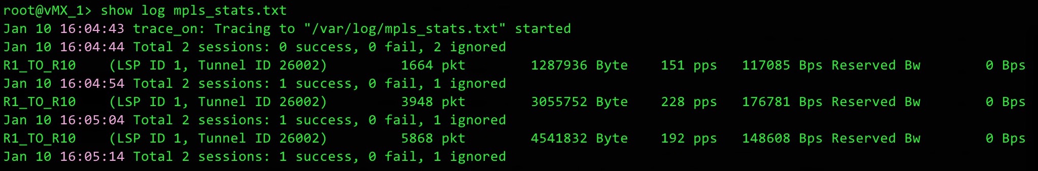
As you can see, the info is very human-readable. If you look at a single line then you’ll notice:
- The name of the LSP
- The total bits and packets that have ever gone over the LSP
- The bits and packets per second.
- The bandwidth reserved by this LSP (currently 0bps, because we haven’t yet turned auto-bandwidth on for this LSP)
We see from the purple timestamps that we are indeed storing this info every ten seconds.
Now we have these logs, we can use them to automatically signal the bandwidth that is going over each LSP. Here’s what we’re going to do today: we’ll configure each LSP to check this log file at an interval of our choosing. For the sake of an example, let’s say we check every 5 minutes. This is a deliberate choice: 300 seconds is the very smallest number you can choose.
The very first time this 300 second timer hits zero, the LSP will look at all the bandwidth samples over that 300 second period, and find the largest sample.
The router will then compare this highest bandwidth sample to the bandwidth that was previously signalled by the LSP. If the two numbers are different from each other, above or below a percentage of our choosing, then something magical happens: automation. Let’s find out what the possible outcomes are of this difference in bandwidth.
WHAT HAPPENS WHEN THE LSP REALISES IT HAS NEW BANDWIDTH REQUIREMENTS?
If there’s enough bandwidth along the current path, then the current path is retained. The only difference is that the LSP now signals its new bandwidth requirements, and every interface along the path is updated with the new total bandwidth available.
If there ISN’T enough bandwidth available on the current path, and if all the LSPs have the same priority (in other words, if there’s no LSPs we can kick off to make room for ourselves), then the router will check to see if there’s an alternative path that does have enough bandwidth. Our router does this thanks to our old friend CSPF, or Constrained Shortest Path First. All links with too little bandwidth are pruned from the topology, and we’re left with our constrained topology of links that we can run SPF on.
If there’s an alternative path that meets the bandwidth requirements, then a new path is signalled, the traffic is moved over gracefully, and the old path is torn down.
What if there’s no bandwidth available anywhere? In this case, by default the LSP stays up, and just stays on the existing path. The LSP doesn’t signal the new bandwidth requirement; it just stays quiet about the new jump in traffic. The advantage of this is that the LSP stays up. The disadvantage is that you might experience packet loss from the fact that some links might be maxed out. But if all your links have no bandwidth left, then of course you’re going to get packet loss. That’s science!
It’s at this stage that you will either consider getting more bandwidth, or deciding if certain LSPs carry higher priority traffic than other LSPs. You’ll remember that we talked about LSP priorities in Part 1: you can use the priority system to kick less important LSPs off, and force them to find a new path. If there’s no bandwidth for these lower-priority LSPs, then those LSPs will indeed be torn down. That sounds bad, but it’s actually the whole point of the priority system: you’re asking yourself, in a situation where there’s no bandwidth available anywhere, is certain traffic more important than other traffic? Is it better for all traffic to have some packet loss, or for some traffic to work fine and for other traffic to not work at all? Look deep inside your heart, and surely you’ll find the answer to this eternal question.
OUR TOPOLOGY
If you’ve read Part 1 then you’ll already be familiar with my Famous Ten Router Lab. What makes it famous, you ask? How about the fact that Time Magazine nominated it as Person Of The Year 2018? Didn’t expect that, did you.
Take some time to remember where the routers are on this lab, and maybe even open it up in a separate tab so you can easily refer back to it.
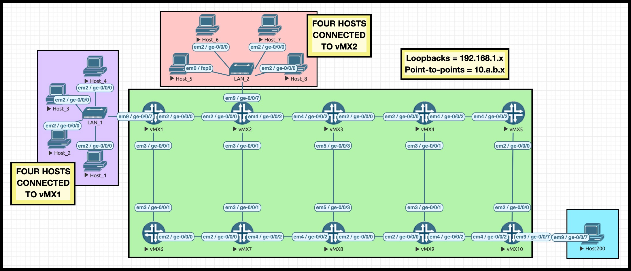
I’ve numbered the IPs on each interface so that we can easily read our RSVP Explicit Route Objects to see where the traffic is going. For example, the IP address 10.3.4.4/24 is the connection between Routers 3 and 4, and the final number shows that we’re at the Router 4 end. The loopbacks are all 192.168.1.x, where x is the router number.
I mentioned in Part 1 about how I’ve manipulated the metrics to force traffic from Router 1 to Router 10 to always take the “top” path: R1, R2, R3, R4, R5, R10.
Notice that both Router 1 and Router 2 have four hosts hanging off of them. I’m going to use these hosts to generate a lot of traffic destined to the host connected to Router 10. You can see that all the links in my lab are 1Gb interfaces, but I’ve actually added this configuration to all my core interfaces:
set protocols rsvp interface all bandwidth 5m
This config doesn’t restrict the bandwidth to 5Mb: it just makes RSVP believe that that’s how much bandwidth is available. Thanks to this config, i just need to send some big rapid pings from a few hosts, and I’ll have effectively “maxed out” the links from the point of view of RSVP. Cheeky!
ADDING AUTO-BANDWIDTH TO ROUTER 1
This config already existed on Router 1:
set protocols mpls label-switched-path R1_TO_R10 to 192.168.1.10
set protocols mpls label-switched-path R1_TO_R10 adaptive
Adaptive isn’t essential here; I’m just in the habit of always adding it. No wonder they called me Best Practices Parker. In Spain I’m known as El Mejores Prácticas. Round the way they call me Dean Martin, because I’m all about those standards.
Anyway, let’s go ahead and add these extra-spicy lines:
set protocols mpls label-switched-path R1_TO_R10 auto-bandwidth adjust-interval 300
set protocols mpls label-switched-path R1_TO_R10 auto-bandwidth adjust-threshold 20
set protocols mpls label-switched-path R1_TO_R10 auto-bandwidth minimum-bandwidth 1k
set protocols mpls label-switched-path R1_TO_R10 auto-bandwidth maximum-bandwidth 100g
What did we just configure? First of all, this LSP is going to check the bandwidth stats file every 300 seconds (aka five minutes) to find the highest sample of bandwidth in that time period. Not the average bandwidth in that time period, but the highest sample in that time period.
I’ve chosen such an aggressive number so that we don’t have to wait in our lab.
PROTIP: in the real world you should consider configuring this as an apply-group, so you can configure it once, and apply it automatically to all your LSPs. You’ll see the most benefit when auto-bandwidth is turned on everywhere, and there’s a high chance that you’ll want the same auto-bandwidth settings on each LSP. Of course, you’ll decide for yourself what is best for your own unique network.
When the LSP comes live for the first time, it will be signalled with a minimum bandwidth of 1k, which we can see below. Notice in red that everything we configured above appears in the output below, along with a countdown for when auto-bandwidth will run next (in 296 seconds time):
root@vMX_1> show mpls lsp name R1_TO_R10 detail
Ingress LSP: 1 sessions

192.168.1.10
  From: 192.168.1.1, State: Up, ActiveRoute: 0, LSPname: R1_TO_R10
  ActivePath:  (primary)
  LSPtype: Static Configured, Penultimate hop popping
  LoadBalance: Random
  Autobandwidth
  MinBW: 1000bps, MaxBW: 100Gbps
  AdjustTimer: 300 secs AdjustThreshold: 20%
  Max AvgBW util: 0bps, Bandwidth Adjustment in 296 second(s).
  Overflow limit: 0, Overflow sample count: 0
  Underflow limit: 0, Underflow sample count: 0, Underflow Max AvgBW: 0bps
  Encoding type: Packet, Switching type: Packet, GPID: IPv4
  LSP Self-ping Status : Enabled
*Primary                    State: Up
    Priorities: 7 0
    Bandwidth: 1000bps
    SmartOptimizeTimer: 180
    Flap Count: 0
    MBB Count: 0
    Computed ERO (S [L] denotes strict [loose] hops): (CSPF metric: 50)
10.1.2.2 S 10.2.3.3 S 10.3.4.4 S 10.4.5.5 S 10.5.10.10 S
{snip}
We can see as well from the IPs in the ERO that the LSP is going the “correct” way from Router 1 to R2 –> R3 –> R4 –> R5 –> R10. I underlined that bit of the IP to help you to see it.
There’s one final bit of the config above to explain: “adjust-threshold 20“. To see what this does, let’s log onto the four hosts connected to Router 1, and send some huge rapid pings.
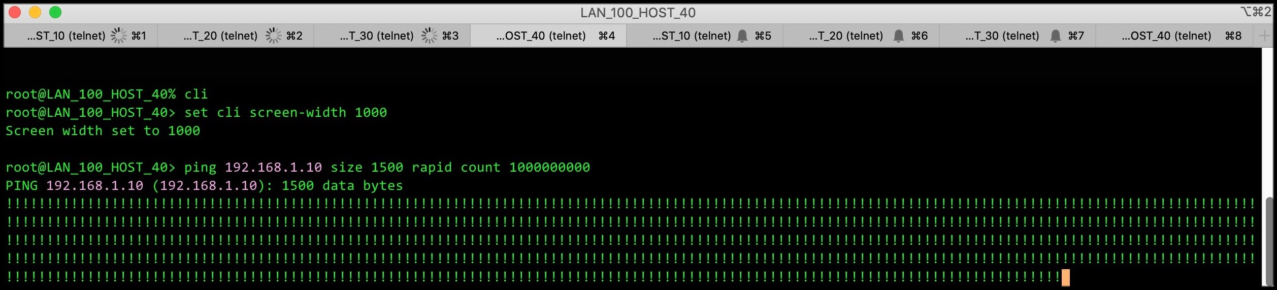
After 300 seconds, the router checks the highest bandwidth sample in those 300 seconds against the 1k bandwidth that the LSP signalled when it came up. If the difference is above or below 20% of the current bandwidth (which it will be, thanks to these pings), the LSP will re-signal with the new bandwidth.
We now need to wait five minutes. Go grab a cup of coffee. Treat yourself!
FIVE MINUTES LATER: THE RESULT ON ROUTER 1’s LSP TO ROUTER 10
While you’re waiting for the countdown, you can check the LSP at any time to see the highest bandwidth stat so far in this adjust-interval:
root@vMX_1> show mpls lsp name R1_TO_R10 detail
Ingress LSP: 1 sessions

192.168.1.10
  From: 192.168.1.1, State: Up, ActiveRoute: 0, LSPname: R1_TO_R10
  ActivePath:  (primary)
  LSPtype: Static Configured, Penultimate hop popping
  LoadBalance: Random
  Autobandwidth
  MinBW: 1000bps, MaxBW: 100Gbps
  AdjustTimer: 300 secs AdjustThreshold: 20%
  Max AvgBW util: 4.5697Mbps, Bandwidth Adjustment in 204 second(s).
{snip}
The wording is a bit confusing there, but the “Max AvgBW” number refers to the largest sampled bandwidth in this period.
Okay, 300 seconds have now gone by. What does the LSP look like now? There’s a lot going on in the output below, and I’ll explain all of the important bits in a moment. Give the output below a read, make a note of the bits in red, and then check out my explanation afterwards.
root@vMX_1> show mpls lsp name R1_TO_R10 extensive
Ingress LSP: 1 sessions

192.168.1.10
  From: 192.168.1.1, State: Up, ActiveRoute: 0, LSPname: R1_TO_R10
  ActivePath:  (primary)
  LSPtype: Static Configured, Penultimate hop popping
  LoadBalance: Random
  Autobandwidth
  MinBW: 1000bps, MaxBW: 100Gbps
  AdjustTimer: 300 secs AdjustThreshold: 20%
  Max AvgBW util: 4.78518Mbps, Bandwidth Adjustment in 260 second(s).
  Overflow limit: 0, Overflow sample count: 0
  Underflow limit: 0, Underflow sample count: 0, Underflow Max AvgBW: 0bps
  Encoding type: Packet, Switching type: Packet, GPID: IPv4
  LSP Self-ping Status : Enabled
*Primary                    State: Up
    Priorities: 7 0
    Bandwidth: 4.83347Mbps
    SmartOptimizeTimer: 180
    Flap Count: 0
    MBB Count: 1
    Computed ERO (S [L] denotes strict [loose] hops): (CSPF metric: 50)
10.1.2.2 S 10.2.3.3 S 10.3.4.4 S 10.4.5.5 S 10.5.10.10 S
    Received RRO (ProtectionFlag 1=Available 2=InUse 4=B/W 8=Node 10=SoftPreempt 20=Node-ID):
          10.1.2.2(Label=300112) 10.2.3.3(Label=300176) 10.3.4.4(Label=300176) 10.4.5.5(Label=300176) 10.5.10.10(Label=3)
   20 Jan 10 17:06:00.506 Make-before-break: Cleaned up old instance: Hold dead expiry
   19 Jan 10 17:04:53.516 Make-before-break: Switched to new instance
   18 Jan 10 17:04:53.515 Self-ping ended successfully
   17 Jan 10 17:04:52.780 Up
   16 Jan 10 17:04:52.780 Automatic Autobw adjustment succeeded: BW changes from 1000 bps to 4833475 bps
   15 Jan 10 17:04:52.779 Self-ping started
   14 Jan 10 17:04:52.779 Self-ping enqueued
   13 Jan 10 17:04:52.779 Record Route:  10.1.2.2(Label=300112) 10.2.3.3(Label=300176) 10.3.4.4(Label=300176) 10.4.5.5(Label=300176) 10.5.10.10(Label=3)
   12 Jan 10 17:04:52.580 Originate make-before-break call
   11 Jan 10 17:04:52.580 CSPF: computation result accepted  10.1.2.2 10.2.3.3 10.3.4.4 10.4.5.5 10.5.10.10
   10 Jan 10 16:59:52.576 Automatic Autobw adjustment failed: while trying for BW changes from 1000 bps to 4661337 bps
    9 Jan 10 16:59:52.576 CSPF failed: no route toward 192.168.1.10
    8 Jan 10 16:54:55.605 Self-ping ended successfully
    7 Jan 10 16:54:54.450 Selected as active path
    6 Jan 10 16:54:54.448 Up
    5 Jan 10 16:54:54.448 Self-ping started
    4 Jan 10 16:54:54.448 Self-ping enqueued
    3 Jan 10 16:54:54.448 Record Route:  10.1.2.2(Label=300096) 10.2.3.3(Label=300160) 10.3.4.4(Label=300160) 10.4.5.5(Label=300160) 10.5.10.10(Label=3)
    2 Jan 10 16:54:52.573 Originate Call
    1 Jan 10 16:54:52.573 CSPF: computation result accepted  10.1.2.2 10.2.3.3 10.3.4.4 10.4.5.5 10.5.10.10
  Created: Sun Jan 10 16:54:52 2021
First of all, we can see that the LSP re-signalled with the new bandwidth: “Bandwidth: 4.83347Mbps“. To prove this, we can quickly go over to Router 3 (a transit router for this LSP), and see how much RSVP bandwidth is available on each interface:
root@vMX_3> show rsvp interface
RSVP interface: 4 active
                          Active  Subscr- Static      Available   Reserved    Highwater
Interface          State  resv    iption  BW          BW          BW          mark
ge-0/0/0.0             Up       1   100%  5Mbps       166.525kbps 4.83347Mbps 4.83347Mbps
ge-0/0/2.0             Up       1   100%  5Mbps       5Mbps       0bps        0bps
ge-0/0/3.0             Up       0   100%  5Mbps       5Mbps       0bps        0bps
lo0.0                  Up       0   100%  5Mbps       5Mbps       0bps        0bps
Of the 5Mb available to RSVP, we can see that 4.83347Mbps is reserved, leaving just 166.525kbps for other LSPs.
Going back to the extensive output of that LSP, at the time we typed that show command we can see that the highest bandwidth sample in the start of this 300 second period is, so far, 4.78518Mbps. That is not 20% more or less than the current sample, so at the end of this 300 second period, as things stand at the moment, the LSP will carry on signalling the same bandwidth as before (4.83347Mbps).
In the LSP logs we see on line 12 that this re-signalling is done in a make-before-break fashion: the new path is signalled, created, and then the old path is torn down. Technically there are two LSPs right now, but they’re signalled in such a way that the bandwidth isn’t double-counted. If you’ve heard of the phrase “shared explicit”, then you’ll know how this magic happens.
I left in line 10 of the logs on purpose to show you something interesting. In my lab I told you I configured all the interfaces at 5Mb for RSVP. Actually though, originally I configured 4Mb on every interface, thinking that it would be enough. Line 10 shows the result: there wasn’t enough bandwidth anywhere in the network to re-signal this LSP, because all my interfaces were 4Mb, and at the time the LSP needed 4.6Mb (4661337 bps). In such situations, RSVP doesn’t tear down the LSP; it just stays on the current path, and that’s what this logs shows. I thought it was worth keeping that in so you could see it. When I noticed this, I changed my interfaces to 5Mb RSVP, and after 300 seconds the LSP re-signalled successfully.
Notice that although the bandwidth changed on this LSP, the path stayed exactly the same. Just like I said! Damn I’m good.
LET’S BRING ROUTER 2 INTO THE MIX
Let’s now add exactly the same config to Router 2. The only difference in this config is the name of the LSP:
set protocols mpls statistics file mpls_stats.txt size 5m files 10
set protocols mpls statistics interval 10
set protocols mpls label-switched-path R2_TO_R10 to 192.168.1.10
set protocols mpls label-switched-path R2_TO_R10 adaptive
set protocols mpls label-switched-path R2_TO_R10 auto-bandwidth adjust-interval 300
set protocols mpls label-switched-path R2_TO_R10 auto-bandwidth adjust-threshold 20
set protocols mpls label-switched-path R2_TO_R10 auto-bandwidth minimum-bandwidth 1k
set protocols mpls label-switched-path R2_TO_R10 auto-bandwidth maximum-bandwidth 100g
As expected, this second LSP comes up, and reserves 1k of bandwidth:
root@vMX_2> show mpls lsp ingress extensive
Ingress LSP: 1 sessions

192.168.1.10
  From: 192.168.1.2, State: Up, ActiveRoute: 0, LSPname: R2_TO_R10
{snip}
    Bandwidth: 1000bps
{snip}
    Computed ERO (S [L] denotes strict [loose] hops): (CSPF metric: 40)
10.2.3.3 S 10.3.4.4 S 10.4.5.5 S 10.5.10.10 S
We can see that this LSP is going along the “top” path, just like Router 1 did. This is what we want, because in a moment I’m going to massively increase the bandwidth going over this LSP, and we’ll see how it reacts to the fact that there is no longer enough bandwidth on the current path.
If we go to Router 3, we can see that the available bandwidth on the interface has gone down by an entire kilobit, thanks to this new LSP:
root@vMX_3> show rsvp interface
RSVP interface: 4 active
                          Active  Subscr- Static      Available   Reserved    Highwater
Interface          State  resv    iption  BW          BW          BW          mark
ge-0/0/0.0             Up       2   100%  5Mbps       165.525kbps 4.83448Mbps 4.83448Mbps
ge-0/0/2.0             Up       1   100%  5Mbps       5Mbps       0bps        0bps
ge-0/0/3.0             Up       0   100%  5Mbps       5Mbps       0bps        0bps
lo0.0                  Up       0   100%  5Mbps       5Mbps       0bps        0bps
Our experiments have shown us that if we get four hosts to ping rapidly with a 1500 packet size, the result is approximately 4.8Mb of bandwidth. Therefore, if we were to generate roughly the same amount of ping traffic on the four hosts connected to Router 2, then it would be clear that the total bandwidth of the R1_TO_R10 LSP and the R2_TO_R10 LSP would easily exceed 5Mb. Excellent: let’s do it!
I’ve set off all the pings in the world, on all eight hosts. Let’s wait 5 minutes, and then check in on what impact this has on the LSP we made on Router 2.
LET’S SEE AN LSP RECALCULATE A NEW PATH WITH THE REQUIRED BANDWIDTH
You just started reading this paragraph straight away, but behind the scenes I had to wait for five minutes. And oh boy did I have fun during that time! I got married twice, divorced four times (don’t ask) I baked a lovely quiche, and I even had time to invent a new kind of spade. Sadly though, I don’t have time to tell you about any of it.
After five minutes, the total traffic over both of these LSPs is way over 5Mb. Let’s check the extensive output of the R2_TO_R10 LSP. Once again the output is long, so take a moment to spot the bits in red, and then check out my description afterwards.
root@vMX_2> show mpls lsp ingress extensive
Ingress LSP: 1 sessions

192.168.1.10
  From: 192.168.1.2, State: Up, ActiveRoute: 0, LSPname: R2_TO_R10
{snip}
*Primary                    State: Up
    Priorities: 7 0
    Bandwidth: 3.69043Mbps
    SmartOptimizeTimer: 180
    Flap Count: 0
    MBB Count: 1
    Computed ERO (S [L] denotes strict [loose] hops): (CSPF metric: 60)
10.2.7.7 S 10.7.8.8 S 10.8.9.9 S 10.9.10.10 S
    Received RRO (ProtectionFlag 1=Available 2=InUse 4=B/W 8=Node 10=SoftPreempt 20=Node-ID):
          10.2.7.7(Label=299840) 10.7.8.8(Label=299840) 10.8.9.9(Label=299840) 10.9.10.10(Label=3)
   17 Jan 10 17:23:59.034 Make-before-break: Switched to new instance
   16 Jan 10 17:23:59.032 Self-ping ended successfully
   15 Jan 10 17:23:58.250 Up
   14 Jan 10 17:23:58.249 Automatic Autobw adjustment succeeded: BW changes from 1000 bps to 3690432 bps
   13 Jan 10 17:23:58.249 Self-ping started
   12 Jan 10 17:23:58.249 Self-ping enqueued
   11 Jan 10 17:23:58.249 Record Route:  10.2.7.7(Label=299840) 10.7.8.8(Label=299840) 10.8.9.9(Label=299840) 10.9.10.10(Label=3)
   10 Jan 10 17:23:57.072 Originate make-before-break call
    9 Jan 10 17:23:57.072 CSPF: computation result accepted  10.2.7.7 10.7.8.8 10.8.9.9 10.9.10.10
    8 Jan 10 17:18:57.291 Self-ping ended successfully
    7 Jan 10 17:18:57.183 Selected as active path
    6 Jan 10 17:18:57.182 Up
{snip}
First of all, we do indeed see the new bandwidth was signalled, from the line near the top that says “Bandwidth: 3.69043Mbps”.
We also see that the LSP is now going a different way! The logs don’t explicitly say that there wasn’t enough bandwidth on the existing path, but we do see on line 9 of the logs that the LSP has used CSPF to calculate a new best path, and on line 10 we see that this new path is being signalled in a make-before-break fashion. We see that the path goes R2 –> R7 –> R8 –> R9 –> R10. On line 14 we can see that an “Automatic Autobw adjustment succeeded“, and from this we can infer that this CSPF calculation was indeed due to bandwidth.
That, right there, is the beauty of auto-bandwidth. The R2_TO_R10 LSP realised that there wasn’t enough bandwidth along the existing path, so it found a new path all by itself, and went that way instead. No human intervention needed! I’ve worked at ISPs before where the problem of maxed-out lines was solved by manually defining “loose hops” for the LSP to follow, to make it take a different route with more bandwidth available. And that’s fine, it works to an extent, but it definitely doesn’t scale. Much better to let the network take care of itself. Hashtag selfcare.
It’s interesting that the new path isn’t metrically the same as the old path. The new path doesn’t have to be of equal cost: the router will use CSPF to find the next metrically-best path, but it doesn’t have to be equal to the existing path. Ultimately the previous path is no longer available to us, and so the philosophy is exactly the same as if a link had gone down altogether: find the next-best path.
WHAT HAPPENS WHEN THE OLD PATH HAS ENOUGH BANDWIDTH AGAIN?
Let’s imagine that traffic over the R1_TO_R10 LSP dies down a bit, and stops using so much bandwidth. Does this impact the LSP on Router 2, which just re-signalled to a longer path? If there’s enough bandwidth available now, will the Router 2 LSP eventually come back to the newer, shorter path? The answer depends on how much bandwidth is going over Router 2’s LSP.
If, after 300 seconds, the bandwidth remains inside the 20% threshold, it means that nothing has happened to trigger a CSPF recalculation. As such, the traffic will stay on the longer, less efficient path. This is actually the default behaviour of all LSPs: once the path is built, LSPs prefer stability. LSPs stay on the path they originally signalled.
By contrast, when the bandwidth does change by 20% either way, CSPF will be triggered, at which point CSPF will see the new better path (which is ironically the old better path); and it will be built. So chances are that the better path will be found eventually, but it certainly isn’t immediate.
As it happens, you might actually want LSPs to actively move over to “better” paths. In that case, you should consider combining auto-bandwidth with the optimize-timer command. By default, this timer is disabled. If you add this config to an LSP, or globally under “protocols mpls“, then you can get LSPs to periodically check that their path is indeed the optimal path. We’re living in a glorious automated world!
WHAT NUMBERS ARE SENSIBLE IN THE REAL WORLD?
What would happen in the real world if you used timers as aggressive as in my examples today? Well, it’s probably a very quick short-cut to getting fired!
Imagine a large network with a huge number of LSPs. Imagine taking samples from all of them every 10 seconds, and running CSPF every 5 minutes, constantly re-signalling LSPs. You’d be creating a lot of control plane state, and you could overwhelm your router, or at least stop it from doing more important tasks. Depending on the size and power of your network, the effect of this could be anything from “it’s fine” to “everything’s on fire”.
Realistically, you’ll want far smaller numbers than we used today. But what numbers should you use? That is of course something that only you can decide. Every network is different. But to help you, here are some questions you should ask yourself:
- How powerful are your routers?
- How weak is your weakest router?
- How often does the bandwidth over an LSP change? (Look at the results in a monitoring system with nice pretty graphs, if you can)
- How often does the bandwidth suddenly spike up/drop down?
- Are these spikes tiny, or do they overwhelm an interface?
- How long do the spikes last for?
- Indeed, what are the bandwidth patterns in general over a day, a week, even a month?
- How many LSPs go over a particular interfaces, and are there any interfaces where the traffic regularly runs particularly hot?
- Do a large number of your LSPs all happen to think a certain path is best, while lots of other links of lower metric go totally unused?
Shorter times will definitely have an impact on your CPU and on your other routers. So for example, re-signalling every 30 minutes isn’t necessarily wrong, but it is fairly aggressive, and you need to be aware of that, what the consequences/advantages/disadvantages are. Two hours is easier on your CPU, and six hours even more so. But do those numbers allow you to react in time?
In regards to how often to sample, again it depends how detailed you want to be. I’m using 10 seconds in this lab, which is clearly silly for the real world. I’ve seen everything from 5 minutes to two hours. A sensible approach would be to turn on the statistics collection first, and use long sample times. Maybe sample every hour. Leave it running for a while, look at your CPU, and confirm that the creation of the stats collection hasn’t had an impact. Then, go to 30 minutes then 20 minutes, and so on. (Bear in mind that you get an outage every time you edit this config.)
Bear in mind too that the combination of frequent samples and lots of LSPs can result in logs being constantly written to a hard disk, and this could wear the disk out if it’s constantly being written to. I actually saw this at one previous employer. They sampled every 60 seconds, and each router had a full mesh of about 200 RSVP LSPs to every other router. One day, two separate routers both died at the same time, and TAC diagnosed them as being caused by failed hard disks that had worn out from too many writes. Turns out that both routers also came live onto the network at pretty much exactly the same time, and it was a total coincidence!
OVERFLOW AND UNDERFLOW SAMPLES: REACTING QUICKLY TO TRAFFIC SPIKES
Now here’s a question. Let’s imagine that we sample every 10 minutes, and we recalculate every 3 hours. At the 3 hour mark our LSP looks at the stats for the past three hours, and sees that the maximum bandwidth used was 1Mb. The LSP re-signals with this much bandwidth.
Imagine that for the next hour, the traffic stays broadly the same. But at around that one hour mark, suddenly we see a spike in traffic. Every 10 minutes we start logging approximately 900Mb of traffic going over the LSP. Let’s imagine that it stays that way.
In this situation, we have to wait another two hours for the LSP to actually re-signal the new bandwidth. Depending on your network, this may or may not be fine. It may be that you have enough bandwidth to handle “temporary” traffic spikes, and so waiting for the next re-signalling time causes no problems.
Alternatively, this could cause a big problem. It may be that for the next two hours you’re going to be maxing out the bandwidth on an interface.
It would be quite nice if there was a way to react to spikes more quickly and dynamically. Well, guess what: there is! And we do it like this:
edit protocols mpls label-switched-path R1_TO_R10 auto-bandwidth
set adjust-threshold-overflow-limit 3
set adjust-threshold-underflow-limit 3
I’ve just added this config to the R1_TO_R10 LSP. Remember that this LSP is configured to react if the highest sampled bandwidth is 20% above or below the previous sample. There’s actually a name for each individual sample that matches this requirement: if it’s above then it’s called an overflow sample, and if it’s below then it’s called an underflow sample.
What we’re saying to our friendly Juniper router here is “hey buddy: if you get three overflow samples in a row, don’t wait for the adjust-interval to finish. No sir: re-signal the new bandwidth right away please, or find a new path right away if the bandwidth isn’t available on your path. Thank you very much!”
Same story for underflow: in this config, if we get three underflow samples in a row, we kick into action sooner than our configured countdown.
To see this in action, I actually need to adjust our lab slightly:
set protocols mpls label-switched-path R1_TO_R10 auto-bandwidth adjust-interval 7200
set protocols mpls statistics interval 120
I’m now grabbing MPLS stats every two minutes (120 seconds), and I’m only going to adjust the bandwidth on my LSP every 2 hours (7200 seconds). The reason for this is that my new overflow/underflow config lines will fail the commit in the previous lab, because the numbers are too small. Notice the error that I get when I try to save my overflow/underflow config with the old lab setup:
[edit]
root@vMX_1# commit and-quit
[edit protocols mpls label-switched-path R1_TO_R10]
  'auto-bandwidth'
    MPLS: (Statistics interval * Adjust threshold overflow limit) MUST be greater than minimum adjust interval 300
error: configuration check-out failed
So, now I’ve got four new lines: a slower adjust-interval, a slower polling time for bandwidth stats, and two lines saying that if I get three overflow or underflow samples in a row, things should kick in quicker.
At the moment, I’ve stopped all the pings, so no traffic is being generated. As soon as I commit my config, I check the LSP. It’s signalled that it only needs 1k, which is the minimum we configured it to signal. We also see our new overflow and underflow limits:
root@vMX_1> show mpls lsp name R1_TO_R10 detail
Ingress LSP: 1 sessions

192.168.1.10
  From: 192.168.1.1, State: Up, ActiveRoute: 0, LSPname: R1_TO_R10
{snip}
  Autobandwidth
  MinBW: 1000bps, MaxBW: 100Gbps
  AdjustTimer: 7200 secs AdjustThreshold: 20%
  Max AvgBW util: 0bps, Bandwidth Adjustment in 6994 second(s).
  Overflow limit: 3, Overflow sample count: 0
  Underflow limit: 3, Underflow sample count: 0, Underflow Max AvgBW: 0bps
{snip}
*Primary                    State: Up
    Priorities: 7 0
    Bandwidth: 1000bps
{snip}
    Computed ERO (S [L] denotes strict [loose] hops): (CSPF metric: 50)
10.1.2.2 S 10.2.3.3 S 10.3.4.4 S 10.4.5.5 S 10.5.10.10 S
We can see that the LSP is due to re-signal in 6994 seconds. Let’s see if we can speed that up.
I re-start my big rapid pings from the four hosts attached to Router 1. Slightly after 120 seconds (one sample period in my new config), I look at the output again:
root@vMX_1> show mpls lsp name R1_TO_R10 detail
Ingress LSP: 1 sessions

192.168.1.10
  From: 192.168.1.1, State: Up, ActiveRoute: 0, LSPname: R1_TO_R10
{snip}
  Autobandwidth
  MinBW: 1000bps, MaxBW: 100Gbps
  AdjustTimer: 7200 secs AdjustThreshold: 20%
  Max AvgBW util: 1.92179Mbps, Bandwidth Adjustment in 6896 second(s).
  Overflow limit: 3, Overflow sample count: 1
  Underflow limit: 3, Underflow sample count: 0, Underflow Max AvgBW: 0bps
{snip}
Well, look at that: we see that there’s been one overflow sample! What about slightly after 240 seconds?
root@vMX_1> show mpls lsp name R1_TO_R10 detail
Ingress LSP: 1 sessions

192.168.1.10
  From: 192.168.1.1, State: Up, ActiveRoute: 0, LSPname: R1_TO_R10
  {snip}
Autobandwidth
  MinBW: 1000bps, MaxBW: 100Gbps
  AdjustTimer: 7200 secs AdjustThreshold: 20%
  Max AvgBW util: 4.22305Mbps, Bandwidth Adjustment in 6774 second(s).
  Overflow limit: 3, Overflow sample count: 2
  Underflow limit: 3, Underflow sample count: 0, Underflow Max AvgBW: 0bps
{snip}
As expected, we now see two overflow samples in a row. if the traffic were to now dip back to nothing, this counter would go back to 0. This counter is for the number of successive overflow stats in a row.
Are you excited to see the magic that happens slightly after the 360 second mark?
root@vMX_1> show mpls lsp name R1_TO_R10 detail
Ingress LSP: 1 sessions

192.168.1.10
  From: 192.168.1.1, State: Up, ActiveRoute: 0, LSPname: R1_TO_R10
  ActivePath:  (primary)
  LSPtype: Static Configured, Penultimate hop popping
  LoadBalance: Random
  Autobandwidth
  MinBW: 1000bps, MaxBW: 100Gbps
  AdjustTimer: 7200 secs AdjustThreshold: 20%
  Max AvgBW util: 4.22305Mbps, Bandwidth Adjustment in 7197 second(s).
  Overflow limit: 3, Overflow sample count: 0
  Underflow limit: 3, Underflow sample count: 0, Underflow Max AvgBW: 0bps
  Encoding type: Packet, Switching type: Packet, GPID: IPv4
  LSP Self-ping Status : Enabled
*Primary                    State: Up
    Priorities: 7 0
    Bandwidth: 4.22305Mbps
{snip}
10.1.2.2 S 10.2.3.3 S 10.3.4.4 S 10.4.5.5 S 10.5.10.10 S
{snip}
There we are: the LSP re-signalled early, triggered by three overflow samples in a row. And the 7200 second counter has reset! It’s showing 7197 seconds, which means I typed this command three seconds after the recalculation. Of course, the overflow sample counter has also reset to zero.
It’s clear that this feature allows you to react to traffic spikes much more quickly, which helps you to get the most out of your bandwidth. Equally though, it creates even more CSPF runs, even more RSVP re-signalling, much more work for all the routers in your network. If your router is very powerful, or if your network is small, then this extra work might not even cause your router to sweat. By contrast, if you’re running older hardware or your network is large, you could accidentally create disaster. Think about the numbers, discuss them with colleagues, lab them up, and introduce them into your network slowly so you can monitor the effects.
MISC BONUS TIP YOU’LL LIKE
Don’t want to wait for the timer to count down before you resignal? As it happens there’s a command to make it happen sooner: “request mpls lsp adjust-autobandwidth name R1_TO_R10” would resignal that LSP on Router 1. Interestingly, it doesn’t reset the countdown until the next round of checks. This is very handy in a lab, when you don’t want to have to keep on waiting 300 seconds for something to happen. And it’s pretty handy in the real world if you really need an LSP to re-signal its bandwidth sooner rather than later!
THAT’S IT – FOR NOW. SEE YOU IN PART THREE!
Lots of ISPs run auto-bandwidth with great success. The value it brings is clear. But there is one final trick up our sleeve: if a single LSP is using a large amount of bandwidth, we can actually configure Junos to automatically split the LSP into two or more sub-LSPs, and load-balance between them! This is called a Containerised LSP. In Part 3 we’ll look at how to configure one, and we’ll take a very close look at how they’re built, maintained, and torn down.
Do you use auto-bandwidth in your network? Let me know in the comments! In the mean time, if you enjoyed this post, you’d be doing me a huge favour if you shared it on your favourite social media of choice, or even mailed it to colleagues who might enjoy it.
If you’re on Mastodon, follow me to find out when I make new posts. (2024 edit: I’m also on BlueSky nowadays too. I was once on Twitter, but I’ve given up on it, on account of… well, I don’t need to finish that sentence, do I.)
Fun competition: my 10,000th follower wins a shiny penny! Wow! (Please note: the shiny penny is cursed, and all who have owned this penny have since met a fate worse than death. Do not accept my offer of this cursed shiny penny.)
And if you fancy some more learning, take a look through my other posts. I’ve got plenty of cool new networking knowledge for you on this website, especially covering Juniper tech and service provider goodness.
It’s all free for you, although I’ll never say no to a donation. This website is 100% a non-profit endeavour, in fact it costs me money to run. I don’t mind that one bit, but it would be cool if I could break even on the web hosting, and the licenses I buy to bring you this sweet sweet content.
See you next time for Part 3!


Man, thank you very much for these detailed posts. Really helpful.