

REDISTRIBUTING YOUR ENTIRE IS-IS NETWORK BY MISTAKE: BEWARE THIS DEFAULT BEHAVIOUR!
(You don’t need to be an expert in IS-IS to understand this post, but it is recommended that you at least know the very basics. If you do, read on! And if you don’t, no worries – I’ve got your back! Give my Beginners Guide To IS-IS series a read, and come back when you’re ready.)
Did you know that the first routing protocol was invented in the year 1685? They called it BRP, or Barry’s Routing Protocol, and it involved a town cryer walking down the street shouting out each individual IP address that belonged to each house. It’s true! They called him The Packetman, and he’d wander the town dressed head to toe like a massive TP-Link router, just like kids do nowadays for Halloween.
You could hear his declarations for miles! “Eighty Two Dot Five Dot Seventy Three Dot Sixty One, The Atkins Family, 72 Valley Road. Two Dot Three Dot Ninety Nine Dot One Hundred And Fifty Four, The Jenkins Family, 73 Valley Road…” it’s amazing to think that it took 300 years for someone to work out that it was easier to get computers to do it for us.
Now, I know what you’re thinking. You’re thinking “Chris, none of that happened, you’re lying to me“, and that’s a fair point. But what I would say in response to that is: shut up.
Anyway, we’re not here to talk history: we’re here to talk IS-IS. I was playing in my lab recently when I noticed something really interesting about the default behaviour of this protocol. And to understand it, we need to remind ourselves about IS-IS levels and areas, and how they interact with each other. Put your learning hat on, as we take a walk around the inner workings of IS-IS!
MY SWEET SWEET LAB
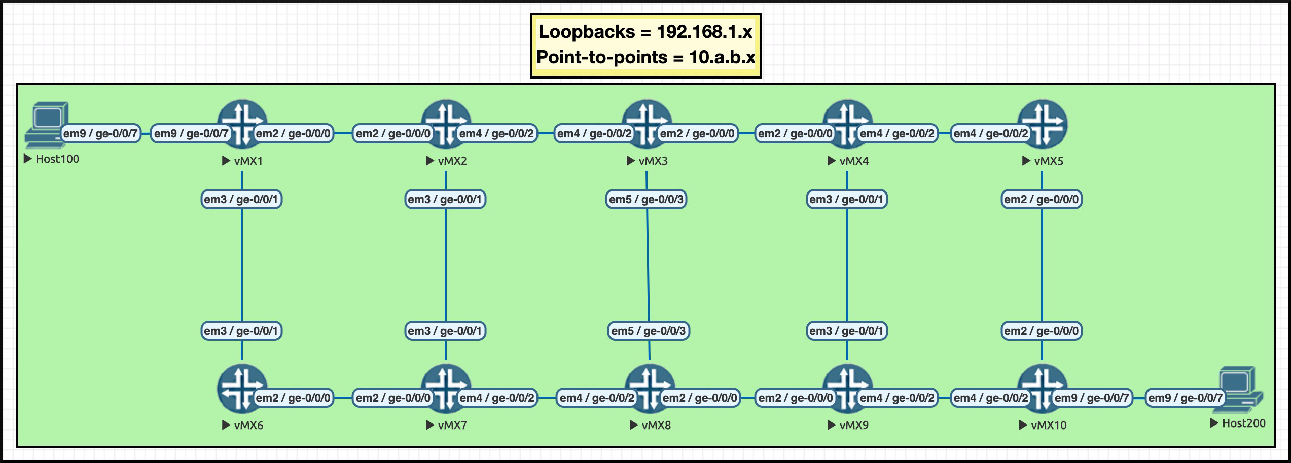
Here’s my topology. Pretty nice, huh? You’ll see this topology in future posts too, so now’s the time to fall in love with it. I’ve numbered the routers, and given the links an IP scheme that works like this: the interface on Router 6 that connects Router 1 to Router 6 is 10.1.6.6/24. VERY nice for reading traceroutes! Click the pic to make it big:
To get my lab up and running, I typed the the laziest command possible:
set protocols isis interface all point-to-point
Let’s set the scene for something we’ll talk about later: you might also know that by default, IS-IS uses “narrow metrics”, meaning that the total metric can be no higher than 64. Remember, these are olden days protocols! But we can easily bring them up to modern standards with the “wide-metrics-only” keyword. You do this under the individual levels, so for example:
set protocols isis level 1 wide-metrics-only
or
set protocols isis level 2 wide-metrics-only
I didn’t have either of these commands on my box, and I wanted to check that a metric to a certain prefix was as I expected it to be. So, I opened up the IS-IS database… and saw something I absolutely did not expect to see..
A REMINDER OF OSPF AREAS VS IS-IS LEVELS
So, before I tell you what I noticed, it’s super important for you to understand this: the concept of an “area” in OSPF and IS-IS are very different indeed. Let’s remind ourselves how OSPF works, and then compare it to IS-IS.
(If you’re absolutely and truly positive that you understand the difference between an IS-IS area and an IS-IS level, and how they interact, you can skip the next four sections. Be honest with yourself though! It’s okay to not know everything!)
In OSPF, areas are a way of dividing a network up into smaller sections so that each router in an area only needs to know the full topology of the area they’re in, and not the larger network in total.
These areas have numbers to identify them. Some OSPF networks simply use Area 0, also known as the backbone, and put all routers into this area. Other networks may have any number of extra areas that connect to the edge of Area 0, like in the picture below. If something in Area 420 wants to get to something in Area 69 (nice), the traffic has to traverse the Area 0 backbone.
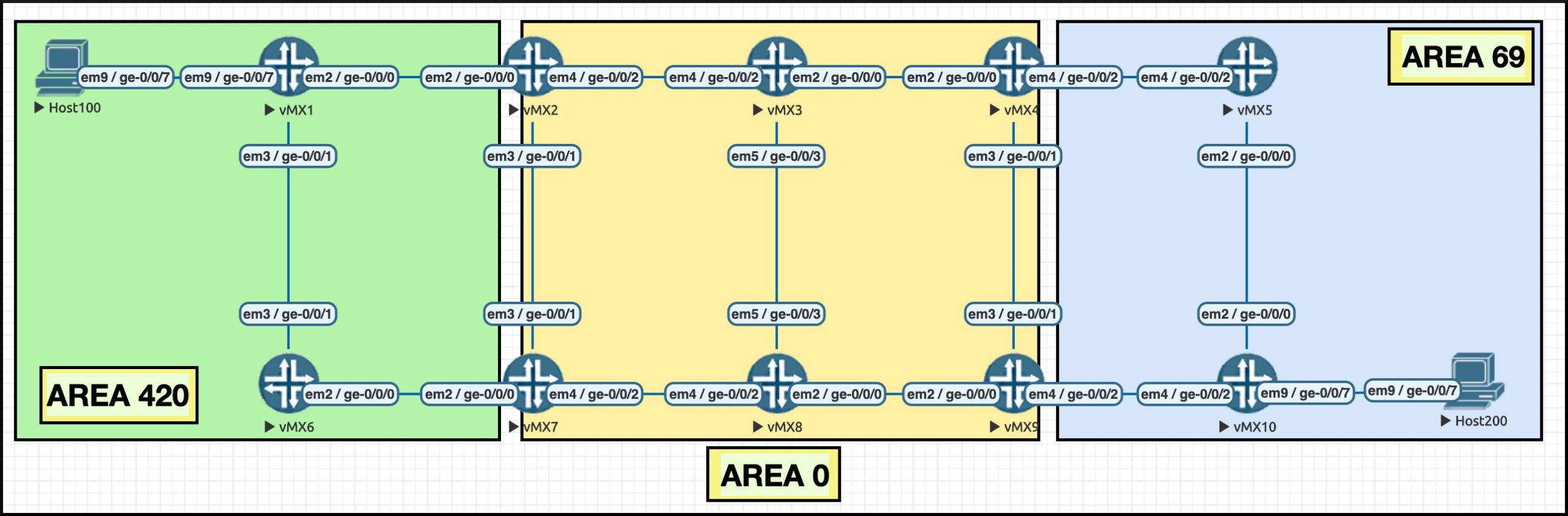
You may also remember that we have the phrase Area Border Router (ABR) to describe those routers which have an interface in Area 0, and also an interface in another area. In the pic above, Routers 2 and 7 are ABRs. So are Routers 4 and 9.
In area 69 (nice), Router 5 only knows the topology of that area. By contrast, Router 4 knows the topology of both Area 0 and also Area 69 (nice), because it has an interface in both areas.
Be sure to understand that you configure the OSPF area on a per-interface basis, not on a per-router basis. You’ll see why that’s important in a moment.
HOW OSPF REDISTRIBUTES PREFIXES
How does a router in one OSPF area learn about prefixes in another area? Well, the actual topology information stays inside an area – but the prefixes from Area 420 are readily advertised into the backbone. The ABR basically sends an advertisement into Area 0 that says “Hey everyone! I know about all these prefixes! If you want to get to them, come to me!”.
Topology changes in Area 420 are hidden from the rest of the network. The ABR will just withdraw that prefix from Area 0, but none of the routers need to re-run the Shortest Path First algorithm to find a new best path everywhere, like they would if an actual line went down. The topology of Area 0 hasn’t changed, after all. Much more efficient!
So, the ABR takes all the OSPF prefixes in Area 420, and re-advertises them into Area 0. You could almost think of this as a kind of redistribution, a bit like Area 420 and Area 0 are two separate OSPF instances. I find it helpful to think in those terms sometimes, because it makes it easier to understand how prefixes travel from one area to another. It’s like there’s a secret routing policy between OSPF areas that just says “If it’s from OSPF, redistribute it from Area 420 to Area 0”.
This re-advertising works in reverse, too. Let’s think about an ABR between Area 0 and Area 69 (nice). This ABR will take all the OSPF prefixes in Area 0 – including the ones that were re-distributed from Area 420 – and re-advertise them into Area 69 (nice).
This is the default behaviour, though there are a number of special “stub” areas available to limit different kinds of prefixes advertised from Area 0 to another area. You need to actively configure this. The default behaviour of OSPF is to re-advertise all OSPF prefixes from area x into area 0, and then from area 0 into area y. What a friendly protocol!
IS-IS LEVEL 2: DIFFERENT FROM OSPF AREAS!
In IS-IS, areas do something different: they simply exist for the benefit of operators to logically divide up their network, for example geographically.
In fact, if we think of OSPF’s Area 0 as a single topology, then the conceptual equivalent in IS-IS has nothing at all to do with areas, and everything to do with something called Level 2.
Here’s how to understand Level 2. We mentioned that OSPF Area 0 is a single topology. Her’e’, another way of thinking of OSPF’s Area 0: you could say it’s nothing more than a collection of OSPF adjacencies between routers that have been configured to be in Area 0. It’s these adjacencies in total that make up Area 0. This makes sense because it isn’t the entire router that’s in an area – it’s only the interface.
Well, with that in mind, IS-IS level 2 is exactly the same! IS-IS Level 2 is nothing more than a series of adjacencies between routers, that have been configured to be in Level 2. The total sum of these adjacencies once again make up the backbone of IS-IS. The difference is that in IS-IS, it genuinely is just a series of adjacencies, because the area a router is in doesn’t matter in the slightest. All that matters is whether two routers that are connected to each other can send a Level 2 Hello to each other. If they can, they become neighbours, regardless of what area they’re in.
(By the way, do you understand the IS-IS addressing format? For example, if I had a router with an ISO loopback address of 49.0001.1921.6801.0001.00, would you be able to identify “49.0001” as the area? If not, then check out this post I wrote a few years ago which includes a beginners guide to the IS-IS addressing format. You’re welcome!)
That’s what I mean about the areas really just being for us engineers, as more of a reference point than anything else. When it comes to Level 2, forget about the area. All that matters is the Level 2.
IS-IS LEVEL 1: LIKE A TOTALLY STUBBY AREA
Now, in exactly the same way that OSPF’s Area 0 can have any number of other areas attached to it via Area Border Routers, similarly in IS-IS our L2 domain can have any number of Level 1 domains attached to it. And it’s at Level 1 that we find that the area number has more significance.
An adjacency will form between two L2 routers regardless of what area they’re in. By contrast, two L1 routers will only form an adjacency if they’re in the same area.
Let’s take a look at this picture below. We see Area 200 on the left, and Area 300 on the right. Notice that a router is completely contained in a single area. This is different from OSPF, where it was the interface that was in an area.
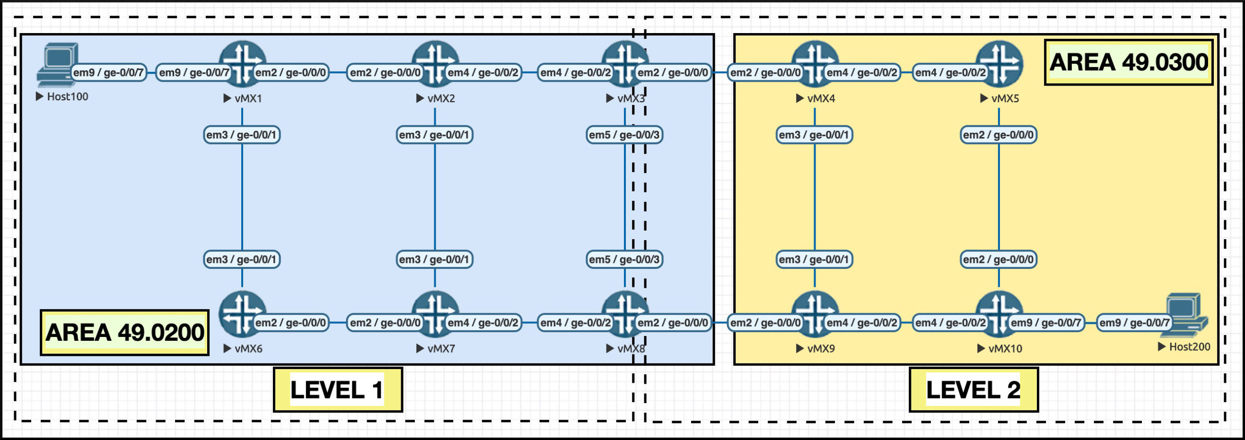
Notice that the dotted line squares show us where Level 1 is, and where Level 2 is. Yep: the level is configured on the interface – just like OSPF areas! Zooming in on Router 3, we see that two of its interfaces are in Level 1. The other interface is in the dotted line square on the right, the one that indicates Level 2.
You can see why people often associate “OSPF areas” with ” IS-IS levels”. However, it isn’t quite correct to say that an OSPF area is exactly the same as an IS-IS level.
First, as we mentioned a moment ago, a Level 2 domain can be made up of multiple areas, which immediately shows that OSPF areas and IS-IS levels can’t be precisely the same thing.
Second, In IS-IS a connection between two routers can actually be both L1 *AND* L2! As a result, there isn’t necessarily a clear demarcation between where Level 1 ends and where Level 2 begins, like there is between areas in OSPF. In fact, it’s entirely possible, and very common, for there to be some overlap between the L1 domain and the L2 domain.
(The true nerds among you will know that you can actually put an OSPF interface into multiple areas as well, to get around some corner-case inefficient routing challenges. But in practice it’s rare to see this in the real world. By contrast, the ability to do this is very much baked into the philosophy of IS-IS.)
Again, this is why I find it helps to think of the L1 network and the L2 network as two separate protocols which happen to talk to each other. When you think of it like that, it’s easier to imagine the two “protocols” overlapping on certain links – in the same way that we could run OSPF in half a network, IS-IS on half of the network, but have both OSPF and IS-IS on certain links that connect the two domains.
A final reason that OSPF areas and IS-IS levels aren’t the same is that it is actually possible to put an entire router into two or more areas at once. And if it is, we actually get one complete L1 domain!
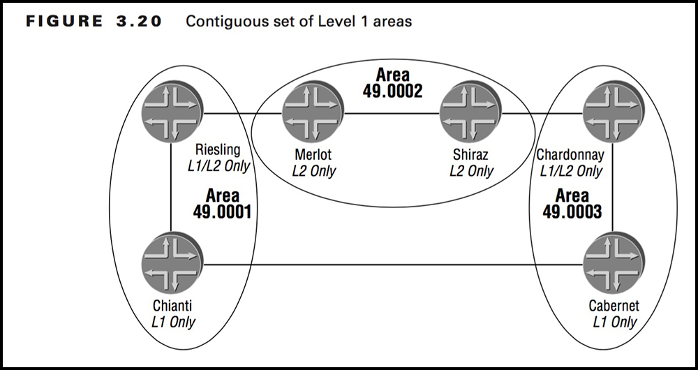
This picture is from the fantastic 2004 Sybex JNCIS book by Joseph M. Soricelli. It shows three areas, with area 2 in the middle as the Level 2 domain. Area 1 and Area 3 are either side of the backbone, like normal. But take a look at that connection between the routers they’re calling Chianti and Cabernet. Do you see that they’re L1 only? Usually these two routers wouldn’t form an L1 neighbour relationship – because they’re in different areas.
But it’s perfectly possible to put one entire router into two different areas at the same time. For example, if we configured Chianti to be in Area 1 and also Area 3, then an L1 adjacency would indeed form between the two routers.
And when this adjacency forms, something Truly Truly Magical happens: we have one complete L1 topology. Riesling will see Cabernet via Chianti. It will also see the prefix via the L2 backbone – but L1 is always preferred over L2, so Riesling will take the path via Chianti to get to Cabernet. This makes sense: if a router is learning a prefix from L1 then it’s actually learning it from the domain that the prefix lives in. If the prefix is also coming from L2, it means the L2 advertisement is almost certainly some other L1/L2 router taking the prefix and redistributing it into the backbone.
It’s clear that OSPF and IS-IS work in slightly different ways! Now we’ve got that down, let’s talk about how prefixes actually move from one area/level to another.
HOW IS-IS REDISTRIBUTES PREFIXES
In the same way that Area Border Routers in OSPF play a role in redistributing prefixes between areas, in IS-IS a router which connects L1 and L2 together will play a role in redistributing prefixes from one level to another. However, the default behaviour in IS-IS is the opposite of OSPF.
In OSPF, the area border router re-advertises all OSPF prefixes from one area to another.
In IS-IS, if a router has a presence in both L1 and L2, the router will still take all the prefixes from L1 and re-advertise them to L2. However, prefixes will NOT be taken from L2 and re-advertised into L1.
In that respect, the IS-IS default behaviour is more like OSPF’s totally stubby area. If you want to advertise something from L2 to L1, you need to create a routing policy to make it happen.
GOOD NEWS MATE: We now know enough theory to see what I learned in my lab. Feeling brave? No? Then hold my hand, and we’ll jump in together.
TURNING ON IS-IS
Let’s go back to the command I used to turn on IS-IS:
set protocols isis interface all point-to-point
Of course, you wouldn’t do this in the real world. But in a lab, it’s quick and easy – IF YOU KNOW WHAT I MEAN!!!!! Haha, brilliant.
Notice that I didn’t explicitly turn on Level 1 or Level 2. In fact, the default behaviour is for both levels to be turned on! I don’t know if this is true of every vendor, but it’s certainly true of Juniper and Cisco. Let’s see what this looks like on Router 3:
root@vMX_3> show isis adjacency
Interface             System         L State        Hold (secs) SNPA
ge-0/0/0.0            vMX_4          3  Up                   24
ge-0/0/2.0            vMX_2          3  Up                   25
ge-0/0/3.0            vMX_8          3  Up                   24
Can I just say that I LOVE the fact that IS-IS actually advertises the hostname of the router. It makes troubleshooting IS-IS so much easier than OSPF, where the Router ID is in the format of an IP address, but doesn’t necessarily have to actually be an IP address. Such a nightmare to read the output!
Take a look at that L column. Can you guess what the 3 means? If you guessed that it means the interface is both L1 and L2, then you’re correct, but it’s not the whole story. See, in IS-IS there’s three different Hello types:
- Level 1 LAN
- Level 2 LAN
- Point-to-point
You probably noticed that I configured my IS-IS interfaces as point-to-point. There’s just one single point-to-point Hello message for both Level types, and a Level type of ‘3″ is the IS-IS way of saying that the interface is in both levels. We see this more clearly if I delete the “point-to-point” keyword from the config on each router:
root@vMX_3> show isis adjacency
Interface             System         L State        Hold (secs) SNPA
ge-0/0/0.0            vMX_4          1  Up                   23  0:5:86:71:45:0
ge-0/0/0.0            vMX_4          2  Up                   23  0:5:86:71:45:0
ge-0/0/2.0            vMX_2          1  Up                   23  0:5:86:71:e6:2
ge-0/0/2.0            vMX_2          2  Up                   23  0:5:86:71:e6:2
ge-0/0/3.0            vMX_8          1  Up                   23  0:5:86:71:e6:3
ge-0/0/3.0            vMX_8          2  Up                   23  0:5:86:71:e6:3
So, both levels are turned on by default, and it is left to operators to decide which level they want to run on which interfaces.
As I mentioned, it’s common for a network to have some links as both L1 and L2, allowing a slight overlap between the two levels. Indeed, this very flexibility is just one of the many reasons that IS-IS can be very attractive to internet providers with large networks who don’t want to be constrained by the area divisions in OSPF – and don’t want to use the multi-area interface config in OSPF in case it introduces extra operational challenges. Remember: wherever possible, keep things simple.
Now here’s a question: what happens if you just leave that default behaviour on, and run L1/L2 everywhere?
The answer is that it can cause two things to happen that you probably didn’t intend to happen. And depending on the size of your network, the consequences could be anything from “not a big deal at all” to “a very big deal indeed”.
WHY CAN IT BE PROBLEMATIC TO LEAVE L1/L2 ON ALL ROUTERS?
First, running both Level 1 and Level 2 everywhere means we’re essentially running two very large topologies on top of each other. Every single box in the network takes part in an L1 domain. Every single box in the network also takes part in an L2 domain. Both domains span the entire network. That means twice the state in all ways – twice the Hellos, twice the keepalives, twice the adjacencies, twice the Shortest Path First algorithm runs every time a link goes up or down. Twice the everything!
There’s no benefit to this doubling of state. The entire network has to do double the amount of work in running the best-path algorithm, once for each level. This is unnecessary, and costs memory and CPU cycles. Remember, L1 will always be preferred over L2, so in this specific scenario the L2 calculation is basically useless.
Having said that, even though L1 is preferred, the correct solution is probably to turn L1 off everywhere, so you’ve just got one large L2 backbone. That way, you can more easily introduce Level 1 domains at the edge in the future, should you wish to do so.
The second problem is less immediately obvious.
Remember that each L1/L2 router takes every single prefix it learns about from Level 1, and redistributes those prefixes into to Level 2. If we were running L1/L2 everywhere, this means that EVERY SINGLE ROUTER will take every single prefix in the entire network, and redistribute them all into Level 2. Each router will therefore claim to be a source that everyone else can use to get to every prefix in the network.
There’s a lot going on there, and it can be tricky to get your head around. So , let’s see what it looks like in practice.
REDISTRIBUTING YOUR ENTIRE NETWORK BY MISTAKE: LET’S SEE IT IN ACTION
Here’s a reminder of our topology. Let’s focus in on Router 1. By the way, ignore the interface that connects to the Host machine. That interface isn’t taking part in IS-IS.
Excluding the R1-to-Host100 interface, there’s three IPv4 addresses on this box:
- The link between 1 and 6 (10.1.6.0/24)
- The link between 1 and 2 (10.1.2.0/24)
- The loopback (192.168.1.1/32).
- There’s also an IPv6 loopback, just for “fun”.
Let’s take a look at Router 1’s Level 1 database. NOTE: I’ve deleted a lot of lines from the output below, to just show you the prefixes, to focus on what we care about today. If you did this command yourself, you’d see a LOT more output.
root@vMX_1> show isis database vMX_1.00-00 extensive level 1
    IPv6 prefix: 2001:db8::1/128 Metric 0 Up
    IP prefix: 192.168.1.1/32, Internal, Metric: default 0, Up
    IP prefix: 10.1.6.0/24, Internal, Metric: default 10, Up
    IP prefix: 10.1.2.0/24, Internal, Metric: default 10, Up
    IP extended prefix: 192.168.1.1/32 metric 0 up
    IP extended prefix: 10.1.6.0/24 metric 10 up
    IP extended prefix: 10.1.2.0/24 metric 10 up
Router 1 is correctly only claiming to be a source for its directly-connected prefixes.
Why do the IPv4 prefixes appear twice? This comes back to the those narrow/wide metrics we mentioned earlier. The “IP prefix” is the Narrow Metric advertisement, and the “IP extended prefix” is the Wide Metric. They’re both advertised by default, which is why the prefixes appear twice. In a moment you’ll see why this matters.
Let’s look at a packet capture to see this narrow/wide metrics stuff in action, and to see what a regular IS-IS advertisement looks like.
Below is the complete Link-State PDU that Router 1 is generating for its presence in Level 1. I’ve expanded out and highlighted the Hostname section. I’ve also expanded out the Prefix sections. In addition, we also see the “Area Addresses” section which lists that area the router is in, and the “IS Reachability” section, which lists the connections to other routers. Remember, IS stands for Intermediate System, which is the old ISO word for a router. Great protocol, terrible name.
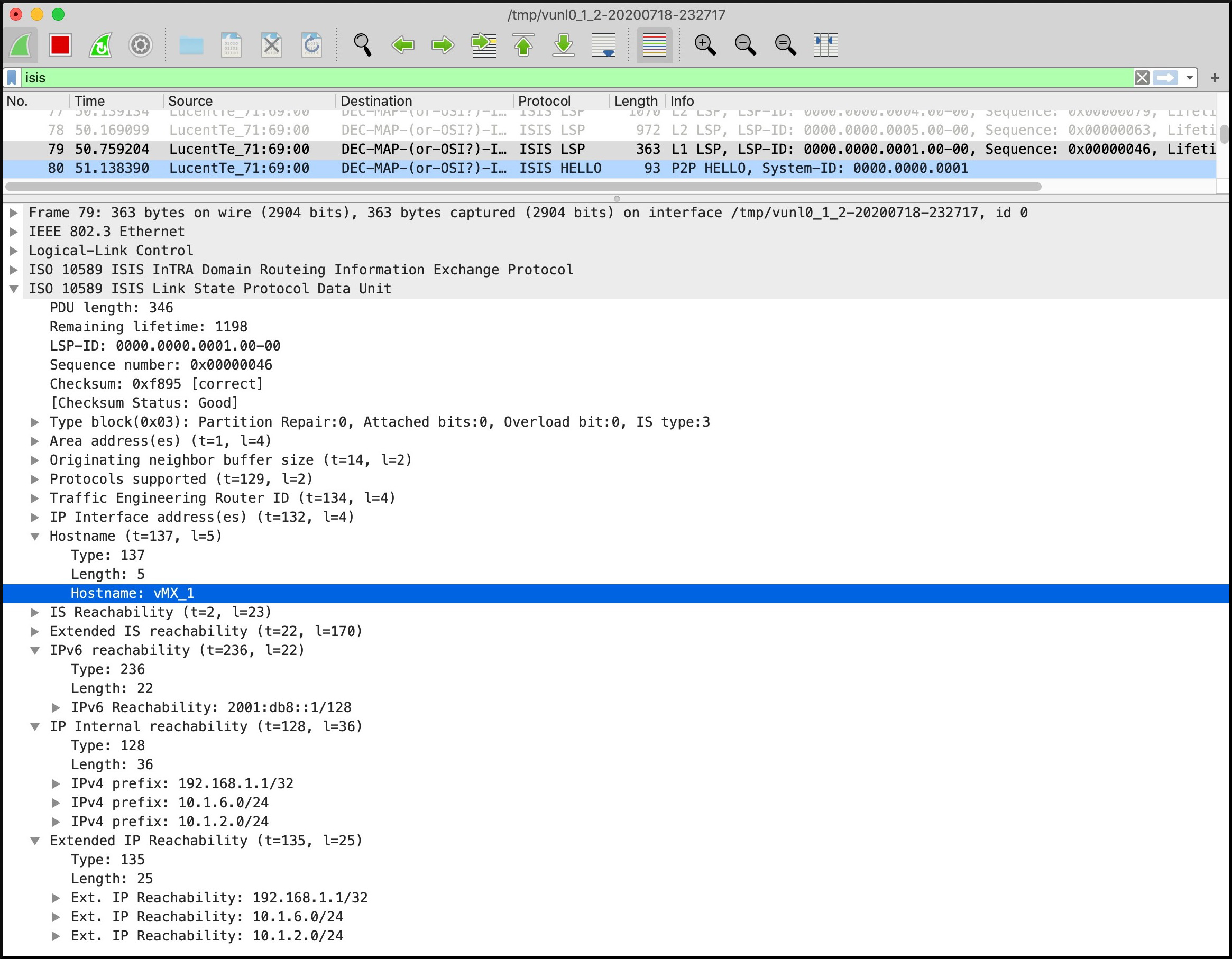
No surprises in Router 1’s Level 1 Link-State PDU there. Everything’s looking good, right? Right?
Well… what if we were to look at the Link-State PDU Router 1 is generating for its presence in Level 2?
Again, I’ve deleted a lot of output to show you just the prefixes. Let’s see what prefixes Router 1 claims to be a source of in the Level 2 domain:
root@vMX_1> show isis database vMX_1.00-00 extensive level 2
    IP prefix: 192.168.1.1/32, Internal, Metric: default 0, Up
    IP prefix: 10.2.3.0/24, Internal, Metric: default 20, Up
    IP prefix: 10.2.7.0/24, Internal, Metric: default 20, Up
    IP prefix: 10.3.4.0/24, Internal, Metric: default 30, Up
    IP prefix: 10.3.8.0/24, Internal, Metric: default 30, Up
    IP prefix: 10.4.5.0/24, Internal, Metric: default 40, Up
    IP prefix: 10.4.9.0/24, Internal, Metric: default 40, Up
    IP prefix: 10.6.7.0/24, Internal, Metric: default 20, Up
    IP prefix: 192.168.1.3/32, Internal, Metric: default 20, Up
    IP prefix: 192.168.1.4/32, Internal, Metric: default 30, Up
    IP prefix: 192.168.1.6/32, Internal, Metric: default 10, Up
    IP prefix: 10.1.6.0/24, Internal, Metric: default 10, Up
    IP prefix: 10.1.2.0/24, Internal, Metric: default 10, Up
    IP prefix: 10.5.10.0/24, Internal, Metric: default 50, Up
    IP prefix: 10.8.9.0/24, Internal, Metric: default 40, Up
    IP prefix: 10.9.10.0/24, Internal, Metric: default 50, Up
    IP prefix: 192.168.1.5/32, Internal, Metric: default 40, Up
    IP prefix: 192.168.1.9/32, Internal, Metric: default 40, Up
    IP prefix: 192.168.1.10/32, Internal, Metric: default 50, Up
    IP prefix: 10.7.8.0/24, Internal, Metric: default 30, Up
    IP prefix: 192.168.1.7/32, Internal, Metric: default 20, Up
    IP prefix: 192.168.1.8/32, Internal, Metric: default 30, Up
    IP prefix: 192.168.1.2/32, Internal, Metric: default 10, Up
    IP extended prefix: 192.168.1.1/32 metric 0 up
    IP extended prefix: 10.2.3.0/24 metric 20 up
    IP extended prefix: 10.2.7.0/24 metric 20 up
    IP extended prefix: 10.3.4.0/24 metric 30 up
    IP extended prefix: 10.3.8.0/24 metric 30 up
    IP extended prefix: 10.4.5.0/24 metric 40 up
    IP extended prefix: 10.4.9.0/24 metric 40 up
    IP extended prefix: 10.6.7.0/24 metric 20 up
    IP extended prefix: 192.168.1.3/32 metric 20 up
    IP extended prefix: 192.168.1.4/32 metric 30 up
    IP extended prefix: 192.168.1.6/32 metric 10 up
    IP extended prefix: 10.1.6.0/24 metric 10 up
    IP extended prefix: 10.1.2.0/24 metric 10 up
    IP extended prefix: 10.5.10.0/24 metric 50 up
    IP extended prefix: 10.8.9.0/24 metric 40 up
    IP extended prefix: 10.9.10.0/24 metric 50 up
    IP extended prefix: 192.168.1.5/32 metric 40 up
    IP extended prefix: 192.168.1.9/32 metric 40 up
    IP extended prefix: 192.168.1.10/32 metric 50 up
    IP extended prefix: 10.7.8.0/24 metric 30 up
    IP extended prefix: 192.168.1.7/32 metric 20 up
    IP extended prefix: 192.168.1.8/32 metric 30 up
    IP extended prefix: 192.168.1.2/32 metric 10 up
    IPv6 prefix: 2001:db8::1/128 Metric 0 Up
    IPv6 prefix: 2001:db8::3/128 Metric 20 Up
    IPv6 prefix: 2001:db8::4/128 Metric 30 Up
    IPv6 prefix: 2001:db8::6/128 Metric 10 Up
    IPv6 prefix: 2001:db8::5/128 Metric 40 Up
    IPv6 prefix: 2001:db8::9/128 Metric 40 Up
    IPv6 prefix: 2001:db8::10/128 Metric 50 Up
    IPv6 prefix: 2001:db8::7/128 Metric 20 Up
    IPv6 prefix: 2001:db8::8/128 Metric 30 Up
    IPv6 prefix: 2001:db8::2/128 Metric 10 Up
HOLY MACARONI BATMAN!! What on earth is going on there?
The problem is that if every single router in the network is both L1/L2 – and therefore every L1 router has learned every prefix in the network via Level 1 – it means that every single router is going to redistribute every single one of those prefixes into Level 2, claiming that it is a source to get to that prefix. And the bigger your network is, the bigger, this list of redistributed prefixes gets. The Level 2 database gets exponentially bigger – and it’s even bigger still if it’s advertising them once again as wide metrics!
If we look at Router 7’s Link-State PDU, we’ll see exactly the same thing. Notice that Router 7 is claiming to be a source for tons of IP addresses that actually belong to completely different boxes! I’ve highlighted a few examples. It’s the same story on every single router in the network.
root@vMX_1> show isis database vMX_7.00-00 extensive level 2
    IP prefix: 192.168.1.1/32, Internal, Metric: default 0, Up
    IP prefix: 10.2.3.0/24, Internal, Metric: default 20, Up
    IP prefix: 10.2.7.0/24, Internal, Metric: default 20, Up
    IP prefix: 10.3.4.0/24, Internal, Metric: default 30, Up
    IP prefix: 10.3.8.0/24, Internal, Metric: default 30, Up
    IP prefix: 10.4.5.0/24, Internal, Metric: default 40, Up
    IP prefix: 10.4.9.0/24, Internal, Metric: default 40, Up
    {snip - you get the idea}
HOW MANY ADDITIONAL PREFIXES ARE WE ADVERTISING BY MISTAKE?
Let’s do some maths, and work out how many prefixes in total are in the Level 1 domain.
On Router 1 we saw that there’s 7 IS-IS prefixes: three “narrow-metric” IPv4, three extended “wide-metric” IPv4, and one IPv6.
From our topology below we see that it’ll be the same story for Routers 5, 6, and 10. Seven prefixes times four routers equals 28 prefixes, so far.
Routers 2, 3, 4, 7, 8 and 9 each have an extra interface, which means one extra standard prefix, and one extended prefix. That’s 9 IS-IS prefixes per box, times 6 routers = 54 total prefixes. And 54 + 28 = 82 IS-IS L1 prefixes. Thus, the L1 domain has 82 IS-IS prefix advertisements in total, for the entire L1 database.
How does this compare to Level 2? Well, to really see it in action, let’s look at a a packet capture of an L2 advertisement in this topology:
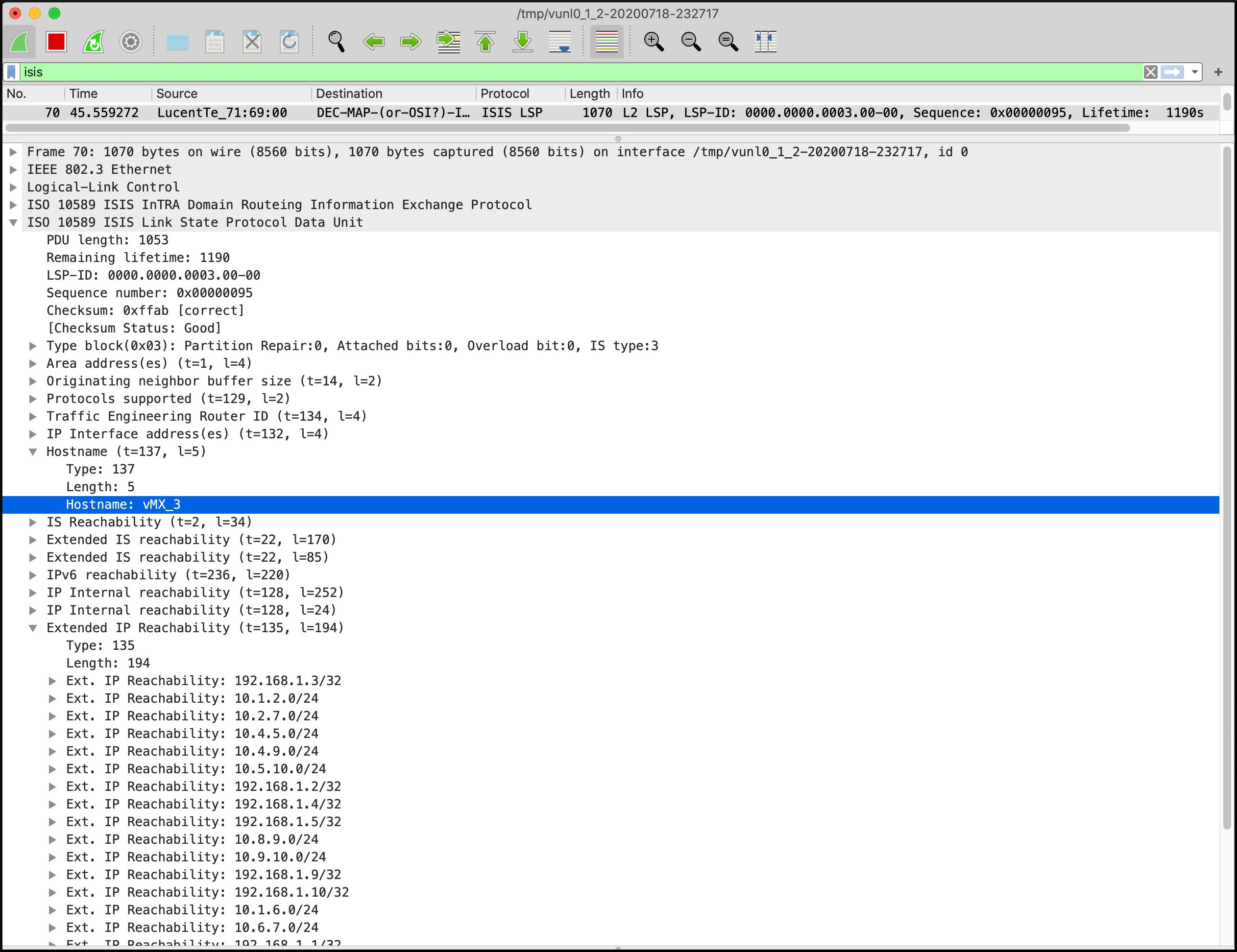
Wow. I’ll save you time: each individual L2 router is claiming to be host to 56 IS-IS prefixes!!
56 prefixes, times 10 routers… that’s 560 prefixes in the L2 domain! Our L2 prefix database is almost seven times larger than the L1 prefix database. Crikey!!
(You might be wondering why it didn’t come out to 820 prefixes, or in other words, the 82 prefixes in Level 1, times ten. The reason is that all the point-to-point prefixes exist twice in the L1 database, as two routers are hosting them. By contrast, Each L2 router will only redistribute the /24 prefix once.)
Remember, the actual topology is exactly the same in both L1 and L2: the increase in the size of the database comes purely from all the additional prefixes, as we saw from that screenshot above.
To some extent, this problem is relieved if you’re using multiple areas. In a network with 200 routers and 10 areas, with L1/L2 turned on everywhere, the L2 network will span the entire topology – but no L1 adjacencies will form between two routers in different areas. As a result, the operator will ] find that they have lots of smaller L1 networks on top of the larger L2 network. The problem of each router redistributing each Level 1 prefix is therefore contained just to the individual Level 1 areas.
So, if you’re using multiple areas around your network, it’s still worth fixing this problem – but it’s less immediately urgent than a 200 router network all contained in the one IS-IS area.
WHAT IMPACT DOES THIS HAVE ON ROUTING?
The good news is that this doesn’t cause routing loops, because both topologies are identical, and in any case L1 is always preferred over L2.
The bad news is that fixing the problem requires downtime, as we’ll see in the next section. And if you only do one router at a time, you might get some inefficient routing.
In our topology above, you would expect a traceroute to Router 5’s loopback from Router 1 to go R1–R2–R3–R4–R5. And indeed, it does:
root@vMX_1> traceroute 192.168.1.5
traceroute to 192.168.1.5 (192.168.1.5), 30 hops max, 40 byte packets
1  10.1.2.2 (10.1.2.2)  8.237 ms  1.918 ms  1.702 ms
2  10.2.3.3 (10.2.3.3)  4.405 ms  2.577 ms  2.509 ms
3  10.3.4.4 (10.3.4.4)  5.352 ms  4.049 ms  4.157 ms
4  192.168.1.5 (192.168.1.5)  6.058 ms  11.093 ms  11.753 ms
But what happens if we completely remove Level 1 from Router 2? The answer is that we create a hole in the L1 topology, that has to be routed around:
root@vMX_1> traceroute 192.168.1.5
traceroute to 192.168.1.5 (192.168.1.5), 30 hops max, 40 byte packets
1  10.1.6.6 (10.1.6.6)  9.905 ms  1.996 ms  1.724 ms
2  10.6.7.7 (10.6.7.7)  10.152 ms  2.851 ms  2.774 ms
3  10.7.8.8 (10.7.8.8)  16.888 ms  6.424 ms  4.996 ms
4  10.3.8.3 (10.3.8.3)  19.919 ms 10.8.9.9 (10.8.9.9)  16.570 ms  7.042 ms
5  10.4.9.4 (10.4.9.4)  21.986 ms  7.579 ms  8.857 ms
6  192.168.1.5 (192.168.1.5)  23.025 ms  8.741 ms  8.404 ms
Yikes! Remember, Router 2 is still up, and the L2 adjacency is still up too. And indeed, Router 1 is learning a path to R5 via the L2 topology. But L1 will always be preferred over L2, so if a router in the middle of your network isn’t talking L1, traffic might go a very inefficient way.
(Interestingly, this lack of L1 won’t affect the way MPLS LSPs are calculated – because by default, RSVP paths are calculated using the IS-IS Level 2 database! So actually, if your Service Provider network is MPLS everywhere, chances are you won’t actually find any problems.)
CAN WE GRACEFULLY REMOVE THE LEVEL 1 CONFIG?
Unfortunately, all the tests in my personal lab showed packet loss when Level 1 was removed. This is because the IS-IS adjacency is torn down and brought back up. I typed this command on Router 2 as an experiment:
root@vMX_2# set protocols isis level 1 disable
Upon committing, notice that the adjacency between R1 and R2 is now L2 only:
root@vMX_1> show isis adjacency
Interface             System         L State        Hold (secs) SNPA
ge-0/0/0.0            vMX_2          2  Up                   22
ge-0/0/1.0            vMX_6          3  Up                   26
If we look in the extensive output, we see logs indicating that the adjacency went down and then came back up:
root@vMX_1> show isis adjacency extensive
vMX_2
  Interface: ge-0/0/0.0, Level: 2, State: Up, Expires in 23 secs
  Priority: 0, Up/Down transitions: 3, Last transition: 00:00:03 ago
  Circuit type: 3, Speaks: IP, IPv6
  Topologies: Unicast
  Restart capable: Yes, Adjacency advertisement: Advertise
  IP addresses: 10.1.2.2
  IPv6 addresses: fe80::205:86ff:fe71:e600
  Transition log:
  When                  State        Event           Down reason
  Sat Jul 18 22:55:19   Up           Seenself
  Sat Jul 18 22:57:11   Down         Level Mismatch  Level Mismatch
  Sat Jul 18 22:57:11   Up           Seenself
Initially I thought this might be because the interface is point-to-point, and therefore there’s only one Hello for both Levels. I reconfigured my network to remove the point-to-point keyword, in other words to have simply “set protocols isis interface all“, so that my router would send two Hellos, one for each level. I then tried disabling level 1 again. Did I get positive results?
Sadly not. We do now see separate adjacencies for L1 and L2, and if we were to do an “extensive” we’d see separate logs for the L1 and L2 adjacencies, which would lead you to believe that the problem is fixed:
root@vMX_1> show isis adjacency
Interface             System         L State        Hold (secs) SNPA
ge-0/0/0.0            vMX_2          1  Down                  0  0:5:86:71:e6:0
ge-0/0/0.0            vMX_2          2  Up                    8  0:5:86:71:e6:0
ge-0/0/1.0            vMX_6          1  Up                    8  0:5:86:71:bf:1
ge-0/0/1.0            vMX_6          2  Up                    6  0:5:86:71:bf:1
However, if you’ve got an MPLS LSP running through this box, you’ll see in the logs that the L1 adjacency going down was enough to trigger a recalculation. A constant ping from Host 100 to Host 200 did indeed see a packet drop. And I probably would have dropped even more packets were it not for the fact that I was running fast-reroute on the LSP (more on that in a future post!).
So as far as I can see, there’s no graceful way of doing this. Perhaps the best way of removing Level 1 is to coincide it with scheduled downtime. Maybe make a list of all the routers in your estate, and tick them off as they go. For example, in our topology above we might one day decide to upgrade Router 3. That would be a good opportunity to also disable Level 1, while the box is being rebooted anyway.
Couple this with a strategy of turning off L1 at the edge of the area first, rather than on boxes in the middle, so that you don’t get inefficient routing paths as a result. And maybe even chuck in the idea of sending flowers to a loved one in your life. Why? Come on, just do it. It’s a nice thing to do! Raise a change request for it if you need to, but definitely do send flowers to the person you love the most.
THAT’S IT!
Have you got any IS-IS stories of your own? If you do, drop me a comment! I’d love to hear them. Tell me about challenges you faced, and things you learned the hard way!
Thank you so much for reading this post. I hope you found it helpful. If you did, you’d be doing me the BIGGEST favour if you shared it on your favourite social media of choice, or even sent it directly to colleagues who might also learn a thing or two.
If you’re on Mastodon, follow me to find out when I make new posts. (2024 edit: I’m also on BlueSky nowadays too. I was once on Twitter, but I’ve given up on it, on account of… well, I don’t need to finish that sentence, do I.)
If you fancy some more learning, take a look through my other posts. I’ve got plenty of cool new networking knowledge for you on this website, especially covering Juniper tech and service provider goodness.
It’s all free for you, although I’ll never say no to a donation. This website is 100% a non-profit endeavour, in fact it costs me money to run. I don’t mind that one bit, but it would be cool if I could break even on the web hosting, and the licenses I buy to bring you this sweet sweet content.
Thanks once again, and all the best of luck with your studies!


>>the L1 adjacency going down was enough to trigger a recalculation.
>>So as far as I can see, there’s no graceful way of doing this.
Take a look at “no-adjacency-down-notification” https://www.juniper.net/documentation/en_US/junos/topics/reference/configuration-statement/no-adjacency-down-notification-edit-protocols-isis.html
To dive even deeper into similar topics I highly recommend this excellent book https://www.amazon.com/Network-Mergers-Migrations-Design-Implementation/dp/0470742372