
RSVP: CREATING MPLS LSPs IN JUNOS (FOR JNCIS-SP STUDENTS)
Last week I had to save the life of an injured frog. This story is completely true, except that instead of “saving” “the life” of an “injured” “frog”, what I actually did last week was “eat” “twenty bags” of an “expired store-brand” “Bombay Mix”.
Does this clarification of the narrative make me any less of a hero? Do I deserve any less praise, any less respect? Of course not. It’s important to not let trivial things like “facts” and “the correct use of words” get in the way of a good story. What matters is that the frog survived. Or, to be more precise, I ate too much Bombay Mix and then felt ill for an entire weekend.
Anyway, forget absolutely every single thing I’ve said up until this point: I’ve written many posts about MPLS and RSVP over the years of this blog. I’ve taught you what RSVP bandwidth reservation is, how auto-bandwidth works, what a container LSP is, what MPLS self-ping is, what inet.3 does, and plenty more.
But for some reason, I’ve never written a post on the basics of RSVP. Just like my frog-saving exploits, I haven’t told you the full story. This is a crime! And as punishment, the judge told me that I could either go to jail for 50 years, or I could write this one blog post. Initially I chose jail, because I’m kind of a tough guy and I reckon I’d be the boss of jail easily, no worries. But then I realised the Wi-Fi there would probably be bad, so I chose to write this post instead.
If you’re new in your MPLS journey and you’ve just embarked on the mighty JNCIS-SP certification, then this post is for you. After we’ve reminded ourselves what an LSP is, we’re going to see how to configure an RSVP LSP, and then take a look at some packet captures to see how the path is created. Let’s do it!
A REMINDER OF HOW MPLS LABELS WORK
I recently wrote an award-winning* post which gave you an introduction to MPLS in general. (*I awarded myself the “Nicest Guy In Blogging” award for this post, and my prize was £20 of my own money.)
This post on RSVP assumes that you’ve read that post on MPLS, or that you know the things it teaches you. If you don’t know what a label is, what a PE router is, what the difference between a transport and a VPN label is, or why we’d use MPLS in the first place, then definitely give that post a read before you read this one!
A key concept in that Intro to MPLS post is the idea of an LSP, or label-switched path. We use RSVP (and other protocols) to create label-switched paths, so before we go on it’s definitely worth looking at the mechanics of one.
Below you can see a diagram which is literally the best I can do. Please don’t judge my poor graphics abilities; instead, take a moment to delight in a graphic made by someone trying their hardest to make you happy.
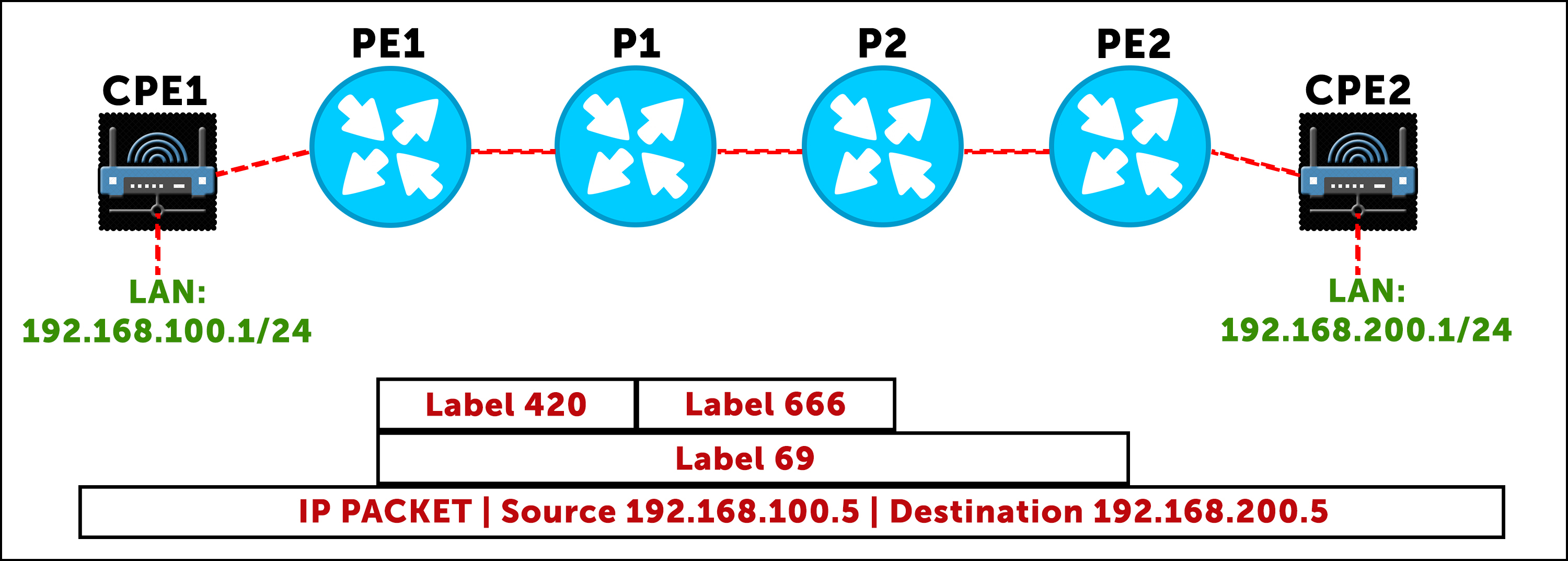
Above we see two customer routers, each with a WAN circuit going to a PE. PE1 and PE2 have a label-switched path between them, with P1 and P2 as transit routers. This customer has a layer 3 MPLS VPN service, which means they can use their private IPs across their entire network, and the service provider will take care of transporting the traffic to each site.
We’re going to follow the journey of a packet which travels from a machine on the LAN on the left, to a machine on the LAN on the right. You can see my clumsy representation of the packet at the very bottom of the diagram above, showing the source and destination IP, which is unchanged from end to end.
When the packet comes in to PE1, two labels are “pushed” onto the packet. First, the label 69 is added. This is the VPN label. Notice that this label stays on the packet all the way across the service provider network, because this label only means something to PE2: it tells PE2 which customer this packet belongs to. This VPN label was learned by BGP.
(By the way, I’ve completely made these labels up, for “fun”. They have no particular meaning. No particular meaning at all.)
Next, a second label is added – an outer transport label. In this example the transport label changes hop-by-hop, because each router has made its own decision about what label it wants to receive when traffic belongs to a certain LSP. The transport label starts as label 420 when PE1 sends the packet to P1. Then, P1 swaps the label to 666 and sends the packet to P2. These labels will have been learned by some kind of MPLS protocol, like RSVP or LDP.
The very last hop in the service provider network is interesting. In the diagram above there’s no label between P2 and PE2. And indeed, as the packet goes from P2 to PE2, there will only be a single label on the packet: the VPN label.
However, in reality, PE2 has told P2 to “use” label 3. This is a special label that actually means “you don’t need to add a transport label to this packet. I’m the final hop in the labelled path, so I’ll be able to process the packet to find out what to do with it.”
This is a nice efficiency: if you think about it, it doesn’t make much sense for PE2 to receive a packet with a transport label. If P2 sent a transport label, then PE2 would have to look up that label, see that it’s the final hop in the LSP, pop the label, and then do a second lookup on the VPN label to find out where to send it. Why make PE2 do two lookups, when it can do just the one?
There’s a name for this idea of not having a label on the penultimate hop: penultimate hop popping, or PHP. It’s the goofiest name for a technology in all of networking. PHP is the default behaviour in many MPLS protocols. It’s well worth remembering that label 3 has this special meaning, because you’ll often see it when you’re following an LSP hop by hop.
WHEN IS A LABEL-SWITCHED-PATH ACTUALLY USED?
To answer this question, let’s return as always to my Famous Ten Router Lab. What makes this lab famous, you ask? How about the fact that it recently won the Booker Prize for its debut novel, “Megabyte Salad”. That do anything for you?
Below you can see an LSP going from R1 to R10. It doesn’t matter what MPLS protocol we used to create this LSP: at the moment we’re just talking about how an LSP gets used by Junos, regardless of how the LSP was created in the first place.
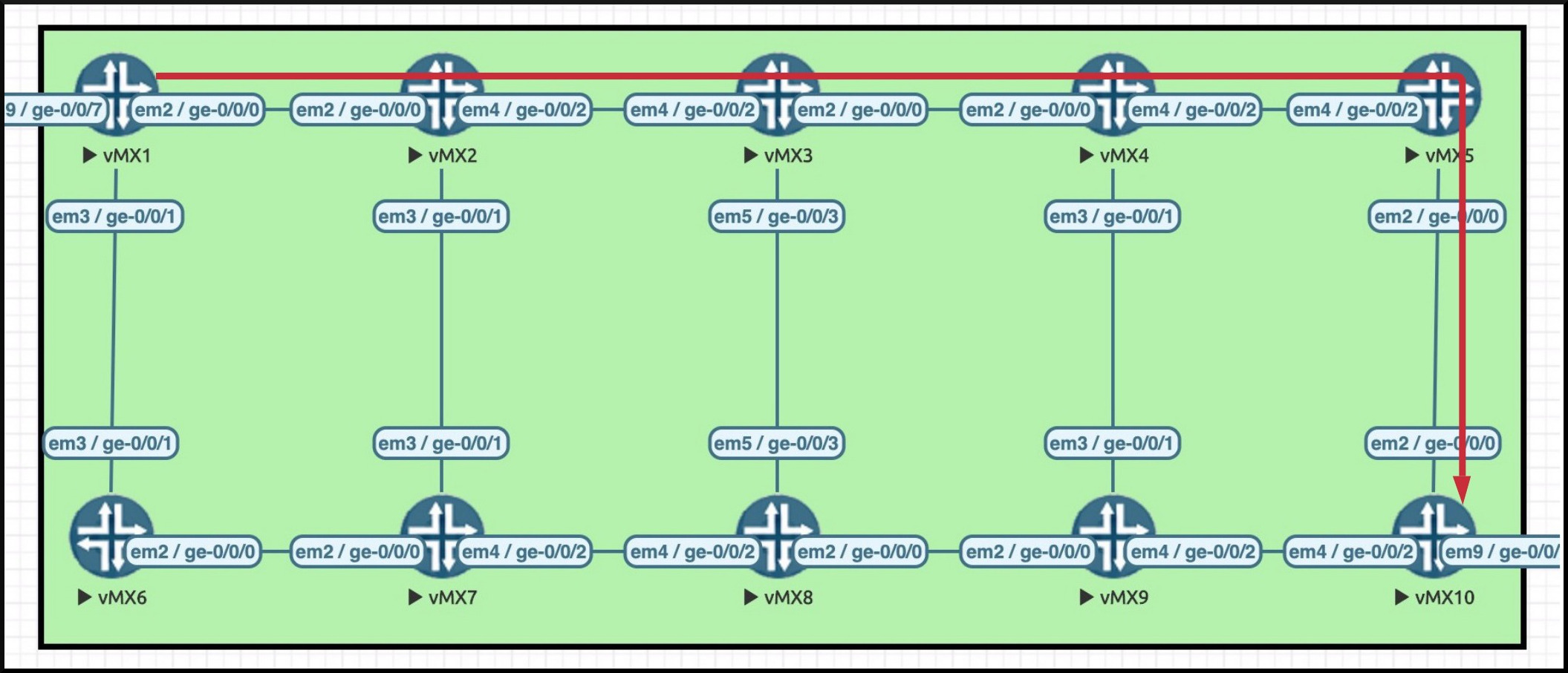
Let’s forget about VPN labels for a moment, and just think about regular IP traffic. In the picture above you can see that R1 has an interface ge-0/0/7 on it. Let’s imagine that this interface is in the default global routing table. When traffic comes into R1 on this interface, how is the decision made about whether to send the traffic down an LSP, or whether to send it unlabelled to whatever the next hop is?
The answer to that question will differ between vendors, but in Junos the default behaviour involves BGP. To understand why, let’s look in a routing table called inet.3, which is where Junos keeps all its LSPs.
The output below is from Router 1 in the diagram above, and shows the existence of the LSP we’ve drawn from Router 1 to Router 10. Notice that there’s one single LSP in this table, going to 192.168.1.10, which is Router 10’s loopback. This LSP happens to have been made by RSVP – and soon we’ll show you how – but all LSPs from all MPLS protocols will be stored this inet.3 table.
root@vMX_1> show route table inet.3
inet.3: 1 destinations, 1 routes (1 active, 0 holddown, 0 hidden)
+ = Active Route, - = Last Active, * = Both

192.168.1.10/32    *[RSVP/7/1] 00:00:03, metric 50
                    > to 10.1.2.2 via ge-0/0/0.0, label-switched-path R1_TO_R10
Now think about BGP. If R10 were to advertise a prefix to R1 via internal BGP, R10 would advertise itself – and specifically its loopback – as the next hop. This is the “next-hop self” that we often configure in internal BGP.
But of course, R1 is not directly connected to R10. If R1 receives an advertisement by BGP with R10’s loopback, 192.168.1.10, as the next-hop, R1 now needs to do a recursive lookup to work out how to get to R10.
In a normal IP network, R1 might decide that the best way to get to R10 is via R6 in the diagram above. R1 would then send the packet to R6, at which point R6 would look up the destination IP address, forward the traffic out of the correct interface, and the process would happen all over again, at each router in the path.
In an MPLS network, this recursive lookup on R1 still happens. But now, R1 has two option. First, its regular IP next-hop like before. Second, it now has a labelled path to R10. This path is stored in inet.3 – and by default, Junos will look in both inet.0 and inet.3 for potential BGP next-hops.
Notice above that RSVP has a route preference (what some vendors call the administrative distance) of 7. LDP has a preference of 9. Both of these beat every single IP routing protocol – and therefore, by default, the most believable “next-hop” will always be an LSP, regardless of what MPLS protocol created it.
Both inet.0 and inet.3 are inspected for potential next-hops for BGP to use. Neither table inherently is more preferred over the other. Rather, it’s the route preference of all the potential next-hops that matters. As such then, if R1 learns something via BGP from R10, R1 will, by default, use the labelled path to send the traffic.
Let’s confirm this. Below, Router 1 has learned a prefix by BGP from Router 10. Router 1 also has an LSP to Router 10. And as such, Router 1 uses this LSP as its “next-hop” to get to Router 10. Nice nice nice!
root@vMX_1> show route protocol bgp
inet.0: 29 destinations, 29 routes (29 active, 0 holddown, 0 hidden)
+ = Active Route, - = Last Active, * = Both

10.10.200.0/24     *[BGP/170] 04:50:18, localpref 100, from 192.168.1.10
                      AS path: I, validation-state: unverified
                    > to 10.1.2.2 via ge-0/0/0.0, label-switched-path R1_TO_R10
HEAD-END & TAIL-END, INGRESS & EGRESS
We actually have a name for the role R1 plays in this LSP: the first router in the LSP’s path is called the head-end router. Sometimes we also call it the “ingress router”, because it’s the router where the packet enters (or “ingresses”) the LSP.
Similarly, the final router in the LSP is called the tail-end router, or sometimes the “egress router”, because it’s the router where the packet leaves (or “egresses”) the LSP.
I’ve sometimes found that newer students get confused by the terms head-end and tail-end, so let’s quickly look at an analogy. Imagine a human standing up. Kind of a nice image, right? But forget that, we haven’t got time to admire this handsome man you just created in your sexy imagination, this human that in your imagination could possibly have my face. What’s important is, if you imagine the man standing under a waterfall (wow, this just got real sexy) then you can imagine traffic flowing downstream, from the head-end to the tail-end. That’s how I remember what head-end and tail-end mean, and also what upstream and downstream means: by imagining a sexy man standing under a waterfall, doing squats without his shirt on, who has my face, and is also me.
RSVP: COMPLICATED, BUT WITH STRONG ADVANTAGES
Now we know what an LSP is, and how they’re used, you’re probably hungry to see how we make them.
You may have heard of a protocol called LDP, which stands for the Label Distribution Protocol. LDP is very simple: you just turn it on, and it then automatically creates LSPs from every router to every other router, giving you a full-mesh of LSPs in your network.
The advantage of LDP is that it’s ridiculously easy to set up. The disadvantage is that all traffic always follows the best path according to IS-IS or OSPF. You have no flexibility to do anything other than this.
By contrast, there is another protocol: RSVP, or the Resource Reservation Protocol. In RSVP, label-switched paths are manually created, from one router to another. In the diagram we saw earlier, if you wanted LSPs from Router 1 to every other router in the network, you would need to create all nine LSPs manually. In addition, RSVP LSPs only go in one direction, so if you need an LSP from Router 1 to Router 10, you also need to configure an RSVP LSP in the reverse direction, on Router 10 going to Router 1.
This sounds like a lot of work. And indeed, it can be. It involves a lot of configuration – and the bigger your network, the more potential config you need. If you’re not using an automation system to make sure you’ve got all the LSPs you need, it’s easy to forget an LSP somewhere.
But although the manual configuration is certainly a downside, RSVP more than makes up for it by offering a very rich set of traffic engineering capabilities.
Remember the list of features that service providers needed from my MPLS post? We gave examples like:
- The ability to send traffic down a very specific path of your choosing
- The ability to create backup paths
- The ability to avoid certain links, or only take certain links
- The ability to monitor the bandwidth of the traffic, and re-route the traffic if there isn’t enough bandwidth available
All these features and more are possible in RSVP.
In RSVP, the head-end calculates the LSP’s path in advance, using the topology information in OSPF or IS-IS. As a result, the head-end router can send a special message, which we’ll see in a moment, telling each router in the path exactly which router the next-hop should be. The head-end does all the thinking – and as long as the resource is available for the LSP to come up, everyone else obeys.
Interestingly though, RSVP does more than just “use the topology”. RSVP doesn’t just know about the links in the network, and their speed – it also knows a lot of extra information, such as the amount of bandwidth that the various LSPs have reserved on each link, or whether certain links are “tagged” to be avoided or to definitely be used.
This enhanced version of the topology is stored in the Traffic Engineering Database, or the TED. It’s thanks to the TED that RSVP is able to do all kinds of cool things that aren’t usually possible.
If you’re using IS-IS (which is my personal preference) then these traffic engineering extensions are enabled by default. If you’re using OSPF then it’s easy to turn on – you just need to add this one command:
set protocols ospf traffic-engineering
It’s for this reason that RSVP is more accurately called RSVP-TE, which you can probably guess stands for Traffic Engineering. Indeed, you’ll see it called RSVP-TE in some documentation, to distinguish it from the original RSVP, which was an attempt to bring Quality of Service to sessions over the internet. Technically speaking, the phrase RSVP refers that old method, and RSVP-TE refers to thing we network engineers use in MPLS. But considering that the old RSVP is dead and buried now, personally I recommend chilling out about the -TE part. Everyone knows what you mean.
By the way, you can probably see why you wouldn’t use a protocol like EIGRP in a service provider network if you need the ability to engineer traffic; the topology information is crucial for RSVP to work.
There’s one other term I’d like you to know: CSPF, which stands for Constrained Shortest Path First. RSVP runs the Shortest Path First algorithm to find the best route, but it doesn’t necessarily run SPF on the entire topology. Instead, RSVP has the ability to prune links from the topology that don’t match our requirements around bandwidth, specific hops that are required, specific links that should be used or avoided, and so on. When you run SPF on this constrained version of the topology, you’re running Constrained Shortest Path First!
ENABLING YOUR NETWORK FOR RSVP LSPs
Let’s learn how to configure an RSVP LSP.
Like all protocols, RSVP needs to be turned on before we can use it. On Router 1 in the diagram above, you can see that ge-0/0/0 is part of our core network. We want it to take part in RSVP LSPs, so we need to do three things:
- We turn on the RSVP protocol on the interface
- We turn on the ability for the interface to talk MPLS
- And we… turn MPLS on again?
set protocols rsvp interface ge-0/0/0.0
set protocols mpls interface ge-0/0/0.0
set interfaces ge-0/0/0.0 family mpls
Why do we turn on MPLS on the interface twice, in two different ways? It’s a good question, and the answer is basically “because of legacy reasons”. In the very olden days of Junos, the architecture of the box required engineers to turn MPLS on in the control plane (“set protocols mpls”), and also in the forwarding plane (enabling the family on the interface itself). It’s a bit odd, but it’s not a big deal: you only need to do it once, and then you can forget about it.
CONFIGURING AND CREATING AN RSVP LSP
Actually configuring an RSVP LSP in Junos is very simple indeed. The only thing to bear in mind is that for some reason it’s done under “protocols mpls”, not “protocols rsvp”. There’s probably some big-brain reason why the wizards behind Junos decided to do this, but I don’t know it. This stumps people who are brand new to all this, so do your best to remember it.
In our diagram above, let’s say I wanted to make an RSVP LSP from Router 1 to Router 10. The config is as simple as this:
[edit]
root@vMX_1# set protocols mpls label-switched-path R1_TO_R10 to 192.168.1.10
We give the LSP a name, we give it a destination… and that’s it!
There’s a lot more that we could do with our LSP – and indeed, in those blog posts I linked to at the start of this post, I show you how to do far more than this – but for now let’s keep it simple.
In the real world we would also need an LSP from R10 to R1. Remember, LSPs are uni-directional. But for now, we just want to see what happens when we create an LSP, so this is fine.
What happens when we commit this change? First of all, I can tell you that the LSP goes this way, just like you saw earlier:
We can confirm that the LSP is up by using this command:
root@vMX_1> show mpls lsp name R1_TO_R10
Ingress LSP: 1 sessions
To              From            State Rt P     ActivePath       LSPname
192.168.1.10    192.168.1.1     Up     0 *                      R1_TO_R10
Total 1 displayed, Up 1, Down 0
Nice! We see our LSP is indeed up. That’s a good start. To find out more, let’s type the same command again, but with “extensive” at the end. There’s a lot of output here, but you can see that I’ve marked important bits in red. I’ll explain what’s going on in a moment.
root@vMX_1> show mpls lsp name R1_TO_R10 extensive
Ingress LSP: 1 sessions

192.168.1.10
  From: 192.168.1.1, State: Up, ActiveRoute: 0, LSPname: R1_TO_R10
  ActivePath:  (primary)
  LSPtype: Static Configured, Penultimate hop popping
  LoadBalance: Random
  Encoding type: Packet, Switching type: Packet, GPID: IPv4
  LSP Self-ping Status : Enabled
 *Primary                    State: Up
    Priorities: 7 0
    SmartOptimizeTimer: 180
    Flap Count: 0
    MBB Count: 0
    Computed ERO (S [L] denotes strict [loose] hops): (CSPF metric: 50)
 10.1.2.2 S 10.2.3.3 S 10.3.4.4 S 10.4.5.5 S 10.5.10.10 S
    Received RRO (ProtectionFlag 1=Available 2=InUse 4=B/W 8=Node 10=SoftPreempt 20=Node-ID):
          10.1.2.2(Label=300176) 10.2.3.3(Label=300240) 10.3.4.4(Label=300128) 10.4.5.5(Label=300016) 10.5.10.10(Label=3)
    8 Apr  9 21:58:47.816 Self-ping ended successfully
    7 Apr  9 21:58:47.747 Selected as active path
    6 Apr  9 21:58:47.746 Up
    5 Apr  9 21:58:47.746 Self-ping started
    4 Apr  9 21:58:47.746 Self-ping enqueued
    3 Apr  9 21:58:47.746 Record Route:  10.1.2.2(Label=300176) 10.2.3.3(Label=300240) 10.3.4.4(Label=300128) 10.4.5.5(Label=300016) 10.5.10.10(Label=3)
    2 Apr  9 21:58:47.677 Originate Call
    1 Apr  9 21:58:47.677 CSPF: computation result accepted  10.1.2.2 10.2.3.3 10.3.4.4 10.4.5.5 10.5.10.10
  Created: Fri Apr  9 21:58:47 2021
Total 1 displayed, Up 1, Down 0
We once again see that our LSP is up. We also see that this is the “Primary” LSP. It’s possible to have backup LSPs that can kick in if the Primary path goes down. Here we only have the one single path, so it is by default the Primary.
There’s a line that says “Computed ERO”. ERO stands for Explicit Route Object, and it’s an explicit path that R1 has created. In other words, R1 calculated the path itself, and then sent a message which told every router in the path what its next-hop should be. By doing this, R1 can be certain that when it send traffic down the LSP, the traffic will definitely take this exact path. In a moment we’re going to look at an RSVP packet capture, and we’ll see this object in the RSVP message that R1 sends.
(By the way, in my Famous Ten Router Lab the final octet in each IP is the router number, which lets us easily see from the ERO that this LSP going R1—R2—R3—R4—R5—10.)
We see some priority numbers. It’s possible in RSVP to give LSPs different priorities, so that if there isn’t enough bandwidth available then a higher priority LSP can actually kick a lower priority LSP off of the path. Brutal, but very useful if you’ve got traffic that is essential above anything else! And hey, guess what: I wrote all about LSP priorities in this post. Wow, I really do treat you well.
At the bottom of the output above we see some logs. If you take it line by line starting from the bottom up, you can see that R1 calculated a path using CSPF (log line 1, highlighted in red above), signalled it (the log on line 2), and that everything was successful.
The “MPLS Self-Ping” bit on lines 4 and 5 is the router’s way of finding out if the LSP is genuinely up. In short, R1 sends a packet down the LSP destined to itself, so that the tail-end will then forward the packet back to the head-end. If the packet boomerangs back to R1, the LSP is proven to be good for forwarding traffic. You can learn more about this process in this post!
So far, so good. Now let’s see what happened on the wire.
WHAT MESSAGES ARE SENT IN RSVP?
RSVP LSPs are set up thanks to two message, one in either direction:
- First, a PATH message goes from the source to the destination, ie from the head-end to the tail-end
- Then, if all goes according to plan, a RESV message will come back in the reverse direction, from destination to source, ie from tail-end to head-end
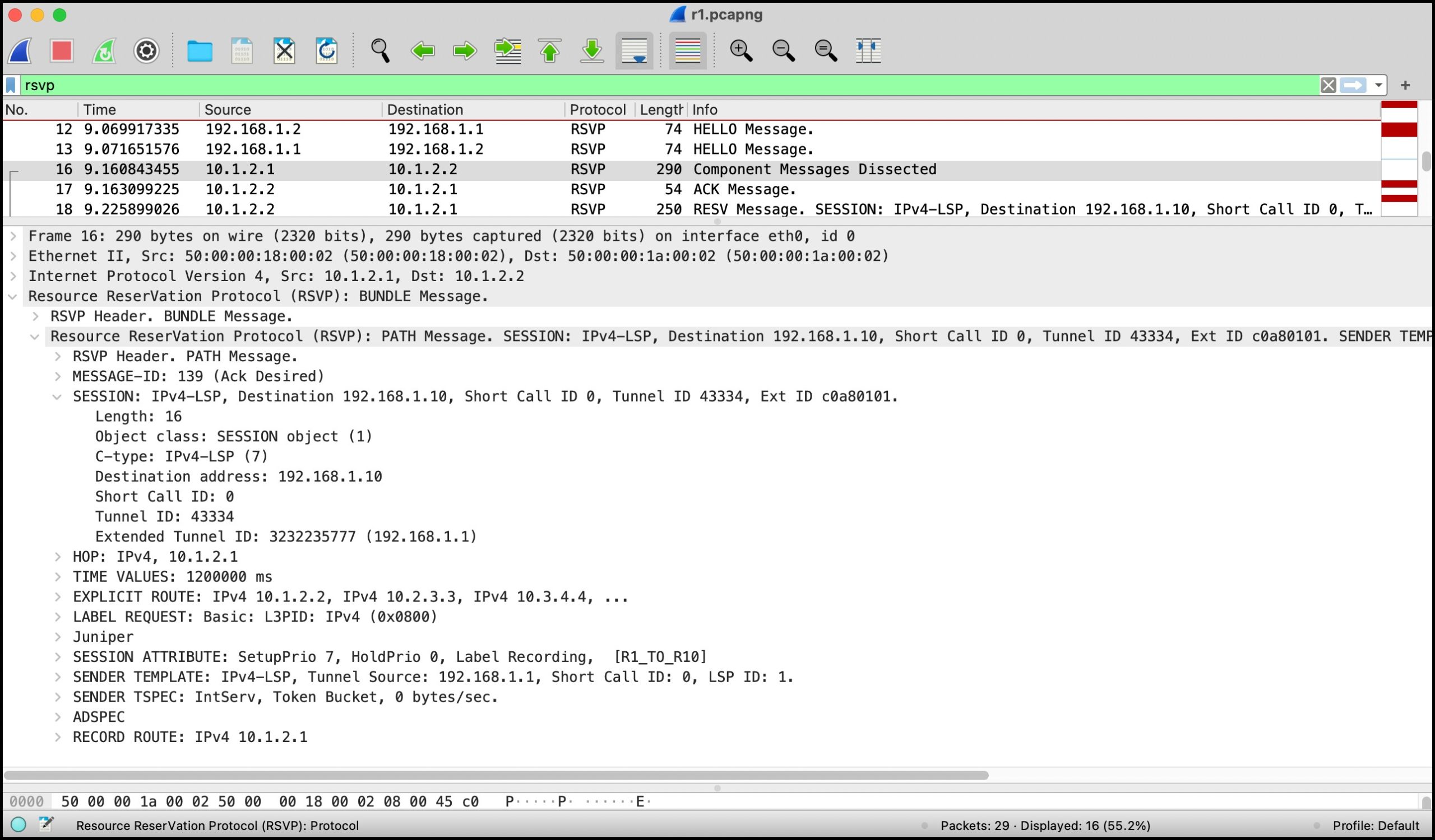
Below you can see a packet capture taken on the link between R1 and R2. I did this packet capture especially for you, as a kind of early birthday present. This means you have to skip a birthday now, and you won’t get any more presents until Christmas.
This screenshot shows 5 RSVP messages, in packets 12, 13, 16, 17 and 18:
- Two Hello messages
- One called “Component Messages Dissected” (This is the PATH message)
- An acknowledgement (which we’ll talk more about in a future post)
- And a RESV message
Click this image to open it up in a new tab, if you want to zoom in on all the fun details:
HELLO MESSAGES
Let’s start with the Hello messages.
Hellos are sent every 9 seconds, and in fact two different Hellos are sent: one from interface to interface, and then one from loopback to loopback. You can see the loopback-to-loopback ones above.
These Hellos contain an object called a “HELLO Request/Ack”, which does what it says on the tin: one router sends a Hello Request, and the other sends a Hello Acknowledgement in reply. There’s a couple of other things in these messages, but they’re not very interesting, so let’s move on to something more juicy: the PATH message.
PATH MESSAGES
Notice in the packet capture above that RSVP message don’t get sent by TCP or UDP; rather, RSVP is its own layer 4 protocol.
RSVP has the ability to bundle many messages together, for efficiency, which is why the name of the layer 4 header in the packet capture above says “Resource ReserVation Protocol (RSVP): BUNDLE Message.” As it happens, we have just the one message in the so-called “bundle”: a PATH message. These messages are sent to request the creation of a label-switched-path. Wow, the name reflects what it does! What a coincidence!
This PATH message has lots of individual “objects” in it. For example, above you can see that we’ve expanded out the “SESSION” object, which contains the tunnel ID – a number that uniquely identifies the tunnel. This SESSION object also contains the end destination address of the LSP.
In the middle of the packet capture you’ll notice an object called a “LABEL REQUEST”, which is literally R1 asking R2 what label R1 should use when it sends traffic to R2 for this LSP.
Underneath that we see the “SESSION ATTRIBUTE”, where we can see the LSP’s priorities. We didn’t expand this one out, but you can see on that line that the “SetupPrio” is 7, and the “HoldPrio” is 0. Remember, you can read more about LSP priorities here.
There’s one other item I want to draw your attention to: the “EXPLICIT ROUTE” object. I’ve expanded it out below so we can take a look.
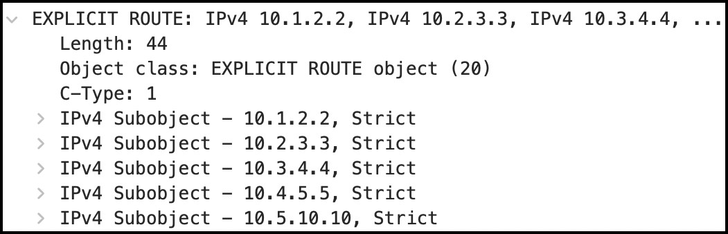
This object contains the exact hop-by-hop path that R1 wants this LSP to take, just like we saw earlier in the “show mpls lsp extensive” output. R1 did the math(s), worked out a “best” path, and added each hop to the Explicit Route Object. In doing so, when R1 passes this PATH message to R2, R2 is able to look at this ERO, see exactly where the path should point to next, and send the PATH message on its way.
Notice that the ERO mentions that these are “Strict” hops. This means it’s mandatory that the next hop is directly connected. If the next hop in the path isn’t a single hop away, the LSP won’t come up. By using strict hops, R1 is saying to each hop “if your link to the next hop fails, don’t try to find an alternative path to get to the next-hop. Instead, tear the LSP down”.
The alternative to a strict hop is a “loose” hop. This kind of hop doesn’t have to be directly connected. Instead, a loose hop tells a router “go via this hop, and get there whichever way is best”. If you have a large international network, you might have a router in the UK with an LSP which you configure to have a loose hop of a specific router in America. You might not care about the exact path on a hop-by-hop level; you just want it to take the best path to the destination that goes via this router in America somehow. By defining your American router as a loose hop, you tell the LSP to go westward around the world, instead of via Europe/Russia/Asia.
R2 will receive this PATH message, remove itself from the PATH, and then send the message onwards. When it removes itself from the PATH, it also adds itself to a new object called the “Record Route” object. In doing so, every router along the way can see the path of the LSP up to that point.
RESV MESSAGES
This PATH message goes all the way to the destination router, the tail-end. In return, the tail-end sends a message in the reverse direction to confirm that all is well, and that the reservation has been successful. This is called a RESV message, and it’s the message that contains all the label information.
Still on our packet capture on the link between R1 and R2, below we see the RESV message that R2 sends to R1. We’ll break down the essential bits in a moment.
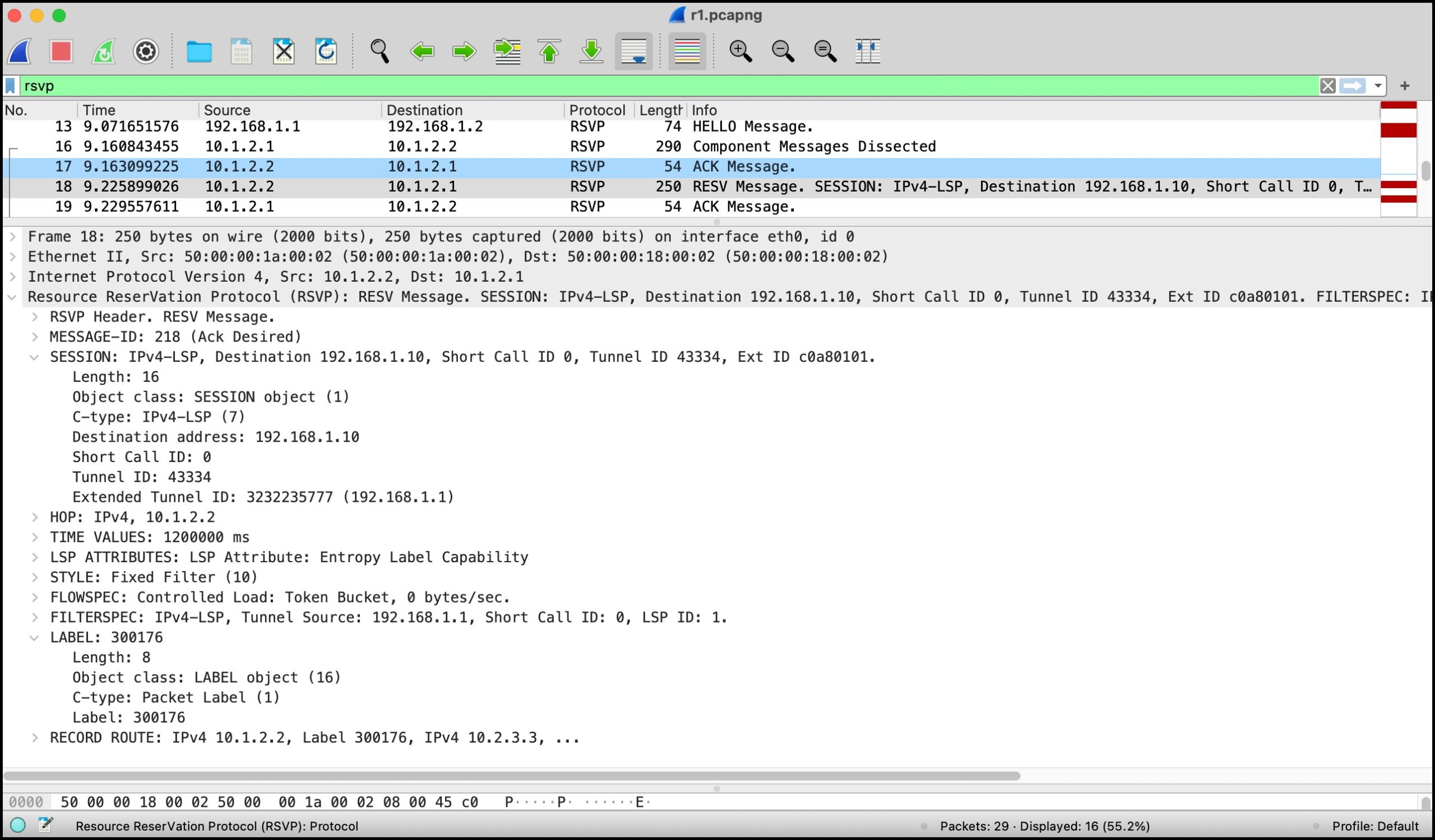
I’ve opened up the “SESSION” object to show that the Tunnel ID matches the one in the PATH message earlier, which is how we know that this is the RESV in response to the previous PATH message.
We also see something called the “STYLE” object. Let’s imagine that for some reason the LSP needs to calculate a new path. In a lot of situations it might be possible to do this in a make-before-break fashion, which means that a new version of the LSP is created, and traffic is moved over gracefully to the new path before the old path is torn down. This is great, but what if the LSP is reserving bandwidth? In this situation, if both old and new paths go over some of the same links, should these links treat the old and new LSPs as two separate LSPs from the point of view of the bandwidth reservation? Or, should they be bundled together as one?
The style you choose will decide the answer to this question. The style above is ‘Fixed Filter”, which is kind of a confusing name, but basically means that the bandwidth will be double-counted. This is the default for a basic LSP like ours. The alternative is “Shared Explicit”, and like the name says, the bandwidth is shared in this style.
Perhaps most importantly we see a “Label” object. As you can imagine, this is R2 telling R1 “if you want to send traffic to me that’s part of this label-switched path, put label 300176 on the packet”.
CONFIRMING THE LABEL
Let’s go over to R2 and see what it will do when it receives a packet with that label.
In Junos, all the labels are stored in a table called mpls.0, and we can use the command below to see what will happen with a particular label
root@vMX_2> show route table mpls.0 label 300176
mpls.0: 7 destinations, 7 routes (7 active, 0 holddown, 0 hidden)
+ = Active Route, - = Last Active, * = Both
300176             *[RSVP/7/1] 00:35:55, metric 1
                    > to 10.2.3.3 via ge-0/0/2.0, label-switched-path R1_TO_R10
The story checks out! This label relates directly to this LSP. This command shows us where R2 will send a packet with this label – but it doesn’t show us the swap action on the label. To see that, we need to add the word “detail” to our command.
Below we’ve zoomed in on the one line that matters for this example: 300176 is swapped for label 300240 before it’s sent on to R3.
root@vMX_2> show route table mpls.0 label 300176 detail | match operation
                Label operation: Swap 300240
By the way, be sure to remember the difference between inet.3 and mpls.0:
- inet.3 is where the LSPs themselves are stored. BGP uses this to resolve next-hops.
- mpls.0 is where the label table is stored. Some vendors call this the LIB, or Label Information Base. If a labelled packet comes in, it’s this table that is consulted to work out how to forward the packet.
WHAT HAPPENS IF THE LSP BREAKS?
We’ve still got our packet capture going.
Now, let’s imagine that the link between Router 3 and 4 breaks. I know, I know: it’s a horrifying thought. You probably dare not even dream of such tragedy. But be brave, and imagine it with me. I’m with you all the way. It’s safe here, it’s very safe.
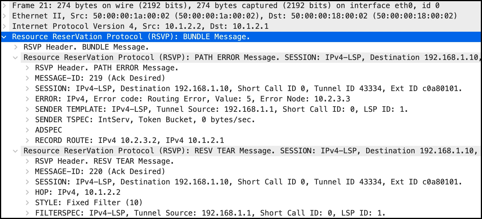
On this particular LSP, Router 3 would send a message called a “RESV TEAR” back towards Router 1, informing Router 1 (and all the routers in between) that the LSP needs to be torn down, and that Router 1 needs to calculate a new best path.
On R3, I’ve shut down the link facing R4. Thanks to our packet capture we can see the ResvTear message arriving at R1, from R2. Actually, notice below that there’s two messages bundled together. Finally, the bundle is actually bundling!
- The first one is a “PATH ERROR”. Pop a pin in that message for now, because we’re going to talk more about what this does in a future blog post when we look at backup paths.
- The second message is a RESV TEAR, and this is the one that matters. This does exactly what it says on the tin: it tears the LSP down.
In response to receiving this message, R1 will indeed tear down the LSP. Once it’s torn down, R1 will calculate a new path, and signal it to be created by sending a PATH message to the new next-hop.
Below we see that the new path happens to go R1—R6—R7—R8—R9—R10:
root@vMX_1> show mpls lsp name R1_TO_R10 extensive | find Computed
    Computed ERO (S [L] denotes strict [loose] hops): (CSPF metric: 60)
 10.1.6.6 S 10.6.7.7 S 10.7.8.8 S 10.8.9.9 S 10.9.10.10 S
{snip}
Shortly after, R4 will also detect that the LSP has gone down. If this were a fibre link then R4 would probably notice it instantly, because it would see that it wasn’t receiving any light from R3. Alternatively, if it’s a copper cable then the link might still be up from R4’s perspective. In any case, after a short while R4 will see that it hasn’t received an RSVP hello from R3, and so R4 will generate its own message to R10 to tear down the LSP.
To be precise, R4 sends a PATHTEAR to R10, which makes sense when you remember that the original PATH message goes towards the tail-end.
By contrast, R3 sends a RESVTEAR to R1, which again makes sense when you remember that the original RESV message goes towards the head-end.
Both of these messages will contain the SESSION object which contains the Tunnel ID, so the routers can be sure they’re tearing down exactly the right LSP.
DOWNTIME WHILE THE LSP RECALCULATES
Let’s spell out the steps involved after we shut down the interface on R3:
- R3 sent a ResvTear message
- R1 received and processed it
- R1 calculates and signals a new LSP
- Traffic is moved onto this new path
This process is relatively quick, but it isn’t instant. It can take anything from a few milliseconds to a fair few seconds for this process to complete, and for traffic successfully flow again. The exact amount of time will depend on how physically large your network is, how many routers are in the path, how busy those routers are at the time that the message is received, how powerful they are, and all that kind of stuff. In my lab it’s almost instant. In an international network with busy routers, it could feel like a lifetime.
One thing is for sure though: during this process, we’ve got an outage.
 Here’s something interesting: during the time it takes for R3 to send the ResvTear message, and during the time it takes for this message to get to R1, R1 will still be sending packets down the LSP. R1 doesn’t know the LSP is down until R1 receives this message. These packets go from R1 to R2, from R2 to R3, and then R3 has no choice but to drop them.
What’s curious about this is that in our topology, we can see that if the R3-R4 link were to go down, R3 has an alternative path via R8 instead.
But can you see the problem here? An RSVP LSP takes a very specific path. The label that R3 would send to R4 means nothing to R8. In short, there is no LSP via R8. This is why, by default, R3 has no choice but to drop the traffic.
Wouldn’t it be nice if there was some way around this? Some kind of pre-signalled backup path that we could use in times of crisis, just temporarily, while a new proper LSP gets created? Indeed it would. And luckily, RSVP offers a number of ways to make this happen.
Sadly though, we’ve run out of time for today. I’ve got cakes to eat, and you’ve got LSPs to lab up. But don’t fear: soon enough I’m going to write a series of posts all about the different kinds of RSVP backup paths, at which point we’ll see even more RSVP messages – and we’ll even dig deeper into how RSVP refreshes LSPs to keep them up. It turns out there’s some recent enhancements to RSVP that makes all this very efficient indeed.
THAT’S IT – FOR NOW!
If you’re on Mastodon, follow me to find out when I make new posts. (2024 edit: I’m also on BlueSky nowadays too. I was once on Twitter, but I’ve given up on it, on account of… well, I don’t need to finish that sentence, do I.)
Bear in mind that I do charge £2000 for you to follow me on any website, plus there’s an extra £4000 daily charge, and also a £6000 hourly charge. This is non-negotiable, and I will send the FBI in to arrest anyone who doesn’t comply.
And hey: if you enjoyed this post, you’d be doing my a very big favour indeed if you shared it on your favourite social media of choice, or sent it directly to pals and colleagues who might get some benefit from it.
And if you fancy some more learning, take a look through my other posts. I’ve got plenty of cool new networking knowledge for you on this website, especially covering Juniper tech and service provider goodness.
It’s all free for you, although I’ll never say no to a donation. This website is 100% a non-profit endeavour, in fact it costs me money to run. I don’t mind that one bit, but it would be cool if I could break even on the web hosting, and the licenses I buy to bring you this sweet sweet content.
In the mean time, if you’re a JNCIS-SP student, you’re now ready to read those posts I linked to at the start. I think you’ll enjoy the journey you’ve embarked on. Be warned though: MPLS is addictive!
Thanks very much for reading, and see you next time!


Hi Criss,
Thanks for your sharing , that is awesome.
may I know how behaviour lsp without no-cspf from your perspective.
Thanks.
When you configure an RSVP LSP with the no-cspf command, it means that the router will not look inside the traffic engineering database to decide the LSP’s path. Instead, the router will only look inside the regular IS-IS or OSPF link-state database.
It also means that the router will not calculate the exact path that the LSP should take.
When you use CSPF, the ingress router uses the TED, the traffic engineering database, to decide the complete path of the LSP. The result is included in something called the ERO, the Explicit Route object, which is the object that lists the precise hop-by-hop path that the ingress router wants the LSP to take. This means that every hop along the way knows exactly what path the LSP should take, and all of the intermediate routers will never let the LSP take a different path. If for some reason one of those hops isn’t available, the LSP simply fails to come up, and the ingress router has to calculate a new path instead. This is a good thing, because you want the ingress router to decide the precise path in a traffic engineered network.
By contrast, when you don’t use CSPF (in other words, when you configure no-cspf), this doesn’t happen. The ingress router runs SPF to calculate the next physical hop, but nothing beyond that. The next hop then has to run SPF to calculate the next hop after that, and so on. This is a bit like in a regular IP network, where Router A might pass a packet to Router B, but then Router B has to work out where the packet needs to go to next.
Wonderful, thanks my friend. Solid technical knowledge ‘spice’ / ‘dressed’ with intelligent humor. In fact I need to thank twice, first to help on my technical refresh and second to allow me good laugh/relax while reading. Again, Wonderful, Congratulations and Thanks!!!
Haha cheers! I’m happy you enjoyed my cooking. 🙂