

Junos: IS-IS Study Notes, Part 4 – Levels, Areas, The Attached Bit, and Default Routes
We’re now halfway through our introductory journey into IS-IS, one of my favourite routing protocols.
You’ve already read Part 1 where I introduced you to the basic mechanics and configuration, and where you learned about IS-IS levels.
Then you read Part 2 where we took a deeper dive into IS-IS messages, including the all-important Hello and LSP message types.
Wow, do you remember Part 3? We learned about the elections that take place on broadcast networks, what a pseudonode is, and how interface types work.
Now it’s time to revisit levels, and introduce IS-IS areas. This is a topic that often confuses new students, and I don’t blame them. It’s a little odd, and unfortunately a lot of documentation doesn’t do a great job of explaining it. You’ll often see explanations of how it’s configured, but rarely will you see people tell you what the actual point of an area is. So hold my hand, and come with me on…. urgh, your hand is slimy. Let’s stop that. Okay, just a moment, I’m going to wash my hands, at which point I’ll come back here and take you on a journey into IS-IS areas. Let’s do it!
DEFINING WHAT AN IS-IS “AREA” IS, AND TWO REASONS TO USE THEM
Before you read this section, make sure you are crystal clear on the idea that an IS-IS area is NOT the same as an OSPF area. As you read this post, I strongly advise you not to compare this too much with OSPF, otherwise you’ll get confused! Do what I say, and thank me afterwards.
In Part 1 you learned that you need to configure an ISO address on a router’s loopback to get devices to talk IS-IS, and that this address contains a section which identifies the “area” that the router is in. I mentioned that the “area” part of the address is a bit like the “network” section of an IP address, while the “System ID” is like the “host” section of an IP address.
For example, in the IPv4 address 192.168.10.5/24, the 192.168.10 part of the address can be called the “network”, and basically reflects the wider subnet. The 5 is the “host” part of the address, and refers to the specific machine within the subnet.
Similarly, in the ISO address “49.1234.1921.6810.0254.00”, the “49.1234” section is the area, and the “1921.6810.0254” bit identifies the host. It’s not exactly the same, but it’s close enough to get your head around the concepts.
An IS-IS router is, by default, entirely in one area. Let’s look at a picture to show you what I mean.
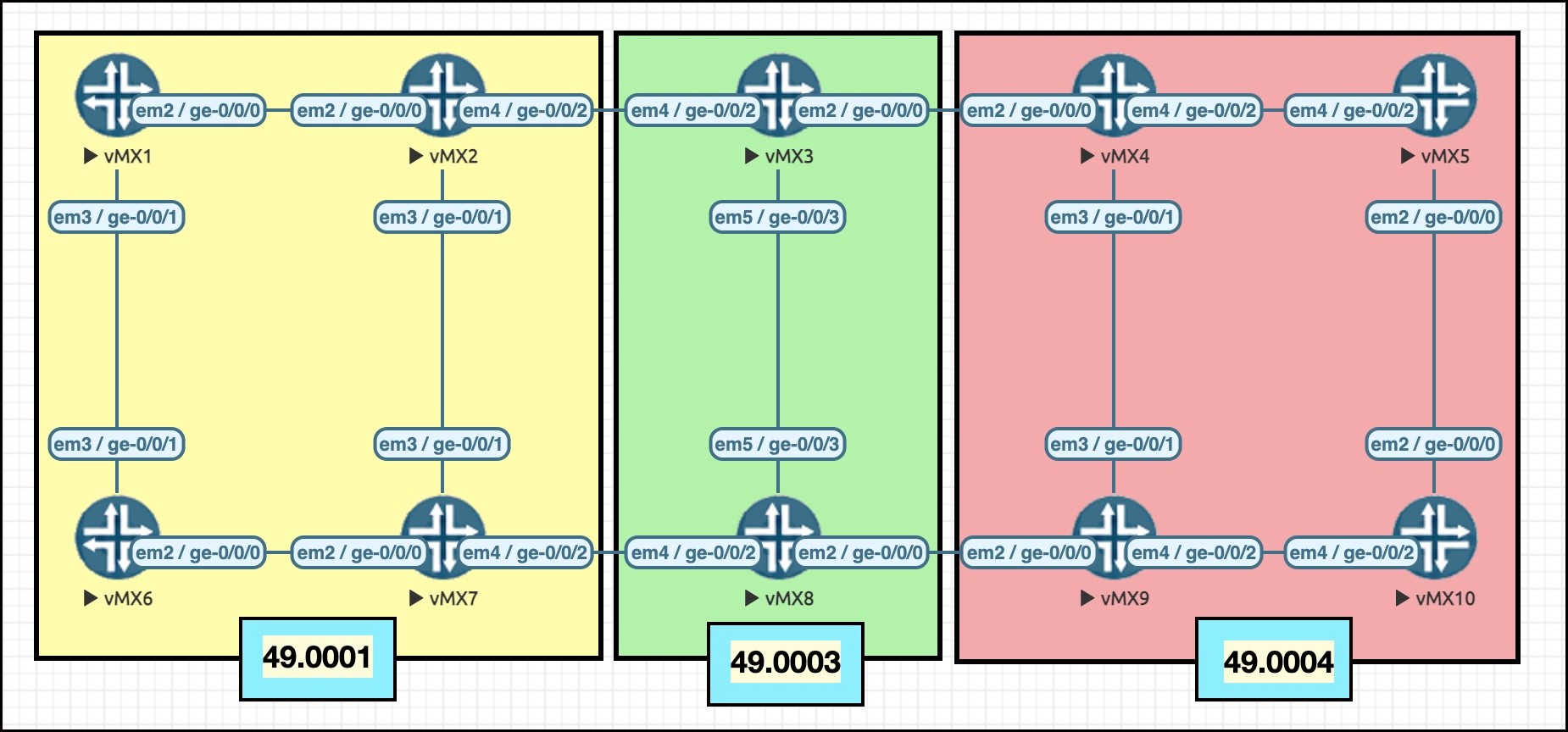
In this picture there are three “areas”: 49.0001, 49.0003, and 49.0004. Notice that every router is entirely in one area. For example, vMX3 is entirely in the area “49.003”.
Okay, fine, but what does it mean to say that something is in an “area”? After all, we’ve already learned that it’s the level that decides the topology. As we’ve seen, an IS-IS level is the equivalent of an OSPF area. So why do we care about IS-IS areas?
Before I answer that, do me a favour: imagine a network of 500 devices, with 200 devices in the Level 2 backbone, and then three Level 1 networks, each with 100 routers, each with some L1/L2 routers that connect the non-backbone part of the network to the backbone. In this scenario, there’s actually nothing stopping you from putting all of these devices into the same IS-IS “area”. This really emphasises how in IS-IS, the “area” has nothing to do with the topology, nothing to do with summarization of information or IPs.
I asked you to imagine that so that you can really, REALLY understand that it’s the level that creates the topology. Now, I’ve talked a lot about what an IS-IS area isn’t – but I’ve still not told you what an IS-IS area is.
To be honest, the bit we’re going to talk about now is the one single thing that I don’t like much about IS-IS. It’s not a big deal, it’s just a bit tricky to get your head around. Having said that, compared to the complexity of OSPF’s many LSAs, area types, adjacency states and confusing rules, the fact that this is pretty much the one thing I don’t like about IS-IS is fairly good going!
The first reason we have IS-IS areas is to do with the formation of adjacencies, and the second is the generation of a default route. Let’s take them each in turn.
REASON ONE: IS-IS ADJACENCIES
Here’s some rules that I want you to remember:
- If two routers are in the same area, they can form a Level 1 adjacency.
- If two routers are in the same area, they can form a Level 2 adjacency.
- If two routers are in the same area, they can form both an L1 and L2 adjacency at the same time.
So far so good. HOWEVER:
- If two routers are in different areas, they can only form a Level 2 adjacency.
- As such, two routers in different areas can NOT form a Level 1 adjacency.
- If you want two routers to form a Level 1 adjacency, they have to be in the same area.
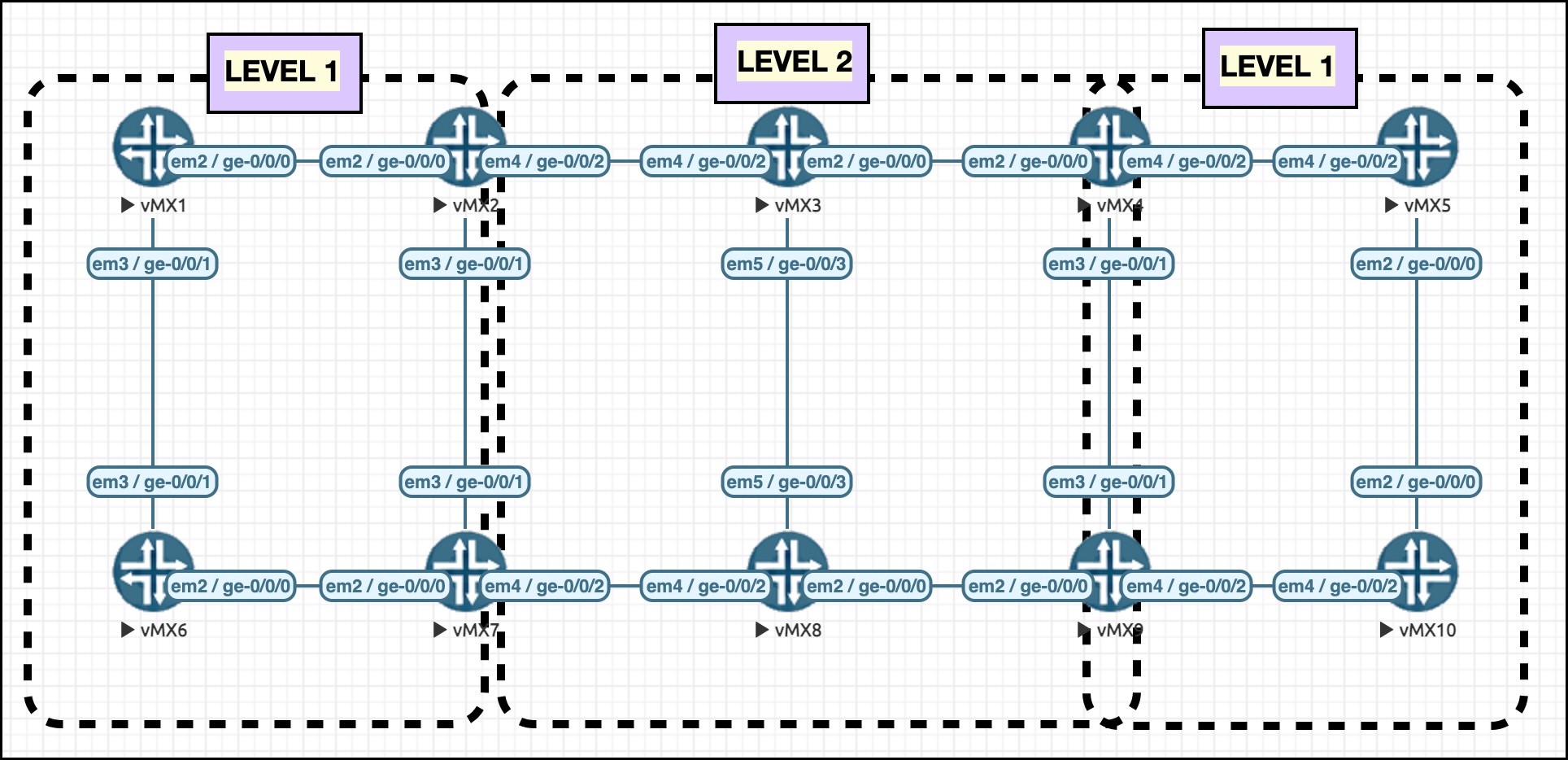
You learned in Part 1 that when you configure IS-IS you can choose to turn off a level on a per-interface basis, or alternatively you can turn a level off completely. With that in mind, notice below that three dotted-line squares have been added to the picture. Each one represents a level, in other words a topology, based on the level configured on the interfaces or router.

Look at vMX_2 (whose name is now a bit obscured – sorry about that!), and notice that it has Level 1 connections to vMX_1 and vMX_7, because it’s in the same area as them. It also has a Level 2 connection to vMX_3. As such, vMX_2 is an L1/L2 border router.
In this topology, vMX_2 cannot form a Level 1 adjacency to vMX_3, because the two routers are in different areas. Only a Level 2 adjacency is possible on that link.
vMX_4 and vMX_9 are interesting: notice that the connection between them is in both Level 1 and Level 2 at the same time. This is totally fine, and common in IS-IS. It means that this link is in both topologies at once. This is possible because the two routers are in the same area. If they were in different areas then they could only have a Level 2 adjacency.
These dotted square boxes are actually the same as you saw earlier in Part 1. The difference this time is that I’ve added areas to the picture.
Okay, fine… but still, what is the point in using areas? After all, you’ve learned that L1–L1, L2–L2, and L1–L2 adjacencies are all possible between two devices in the same area. Every single adjacency type is possible when all routers are in the same area. You’ve also learned that it’s the level that makes the topology, not the area.
So, then, why not just put everything in the same area? What’s the point in all this?? Argh!!
In my personal opinion, the answer to this question entirely depends on whether or not you want your IS-IS L1 routers to automatically have a default route pointing to the L1/L2 router. If you don’t, you can probably just put every single router into the same area. Let’s find out why.
REASON TWO: DEFAULT ROUTES
Do you remember a moment ago when I asked you to imagine a network of 500 routers, with 200 routers in Level 2, and then three Level 1 networks each hosting 100 routers? Get that back into your mind. Remember that I also told you to imagine that all 500 routers are configured to be in the same area. So, a backbone network, three non-backbone networks, and a single area. Let’s say 49.0420, to give you something to imagine.
Wow, I’m really jealous. It sounds like you’re having a really great time imagining it, like maybe something that might become your new happy place.
By default, a device in one of the Level 1 networks won’t know any of the IPs of any router in a different Level 1 network, or any of the IPs in the Level 2 backbone. That’s because, as you learned in Part 1, Level 1 networks are like OSPF totally stubby areas. The L1/L2 router won’t leak anything down into Level 1 by default.
I mentioned before that you could write a routing policy to leak IPs from Level 2 down into Level 1, and soon enough you’ll see an example of that. Ideally though, you might want a default route – and you might like the L1/L2 router to generate it.
Here’s the thing: in the scenario where all 500 routers are in the same area, no default route will be generated by any of the L1/L2 border routers. Even though you’ve got a backbone network, and multiple non-backbone networks attached to it, there’ll be no default route. In addition, there’s no Junos command to generate one, like there is in OSPF with a totally stubby area, and the Junos “default-metric” command.
So, how do we generate a default route? Well, we could create one manually, as a static route or aggregate route with a next-hop of discard, and then redistribute it in. I’ll show you how to do this in a moment. But what if you don’t want to do this, and instead you want IS-IS to create it for you?
This is where areas come in.
THE ATTACHED BIT
Go back to the imaginary 500 router topology, with a backbone network and three non-backbone networks. This time though, imagine that one of the Level 1 networks is 49.0001, another is 49.0002, and another is 49.0003. Each network has at least one L1/L2 router to connect to the backbone.
For simplicity, let’s say that all of the Level 2 only routers are in area 49.0069. Nice.
IS-IS L1/L2 routers have the ability to set something called the “Attached bit” in their Level 1 LSP. This bit says to other routers in that part of the network “I’m able to get to other areas. If you want to break out of Level 1, come to me”. This means that the L1/L2 router doesn’t explicitly advertise a default route; rather, it advertises this functionality by setting that bit in its Level 1 LSP, leaving up to the L1 routers to generate their own default route pointing towards the L1/L2 router. You may remember that you saw that bit in the packet capture in Part 2.
I chose my language precisely there. The L1/L2 border router doesn’t advertise the fact that it can get to different levels; it advertises that it can get to different areas.
Go back to the topology earlier, but this time imagine that everything is in Area 49.0001.
There’s still a Level 2 backbone, and two Level 1 networks attached to it. Do the L1/L2 routers set the attached bit? Amazingly, the answer is: no! In this scenario, the L1/L2 router does NOT set the attached bit, and as such the L1 routers do NOT generate a default route!!
In my opinion, this is madness. I don’t really care that the L1/L2 router can get to different areas. What I care about is that it can get to other levels. And yet, for reasons that I do not understand, the connection to the backbone isn’t enough to generate a default route. It needs to be able to get to different AREAS.
So, if you want IS-IS to generate a default route automatically, you have to use areas.
By the way, we’re going to look at some verification commands in Part 4. For now though, here’s something you can do if you want to test this yourself. Configure a topology like the picture earlier with three areas, and then type the command “show isis database vMX_4 extensive” on any router in the Level 1 network on the right. In this topology, vMX_4 is a L1/L2 router. You’ll see on one line that it mentions the fact that the Attached bit is set in vMX_4’s LSP:
root@vMX_10> show isis database vMX_4 extensive | match Attached
    Checksum: 0x932c, Sequence: 0x1b, Attributes: 0xb <L1 L2 Attached>
Then, reconfigure things so that everything is in the same area. You’ll see that the Attached bit disappears:
root@vMX_10> show isis database vMX_4 extensive | match Attached
    Checksum: 0x6e58, Sequence: 0x1f, Attributes: 0x3 <L1 L2>
DOES THIS MEAN THAT YOU *HAVE* TO USE DIFFERENT AREAS IF YOU WANT A DEFAULT ROUTE?
Having said that, I still think that areas are silly. Like, what’s the point? Why not just put everything into a single area? If you want a default route, you can create one manually with a next-hop of discard, and then make a policy advertising it into Level 1. This gives you the default route you want, plus it makes things more explicit for people reading the config (which is, after all, one of the advantages of having to use policies in the first place to get things from Level 2 to Level 1), plus it means that you’re not restricted in your designs for what routers can form adjacencies if you add things to redesign things in the future.
Let’s take a look at how route leaking works, so we can see how to make that happen.
USING ROUTING POLICY TO LEAK FROM L2 TO L1
vMX_10 is fully in Level 1. What loopbacks is it learning via IS-IS at the moment?
root@vMX_10> show route protocol isis | match /32
192.168.1.4/32     *[IS-IS/15] 00:00:08, metric 200
192.168.1.5/32     *[IS-IS/15] 00:00:08, metric 100
192.168.1.9/32     *[IS-IS/15] 00:00:08, metric 100
It knows the loopbacks of the other three routers in the Level 1 topology, and nothing else.
Let’s add this policy on vMX_9, one of the two L1/L2 routers:
root@vMX_9> show configuration policy-options policy-statement LEAK_L2_TO_L1
term L2_TO_L1 {
    from {
        protocol isis;
        level 2;
    }
    to level 1;
    then accept;
}
This policy has a single term, which just takes everything from Level 2, and puts it into Level 1. You could additionally add a route-filter to restrict it to just a certain range of IPs, for example your loopback range.
This is then added to ISIS with the command “set protocols isis export LEAK_L2_TO_L1“. The result on vMX_10 is that it now knows all the IPs in the network! Here you can see that it’s learned every single loopback.
root@vMX_10> show route protocol isis | match /32
192.168.1.1/32     *[IS-IS/18] 00:03:31, metric 500
192.168.1.2/32     *[IS-IS/18] 00:03:31, metric 400
192.168.1.3/32     *[IS-IS/18] 00:03:31, metric 300
192.168.1.4/32     *[IS-IS/15] 00:10:03, metric 200
192.168.1.5/32     *[IS-IS/15] 00:10:03, metric 100
192.168.1.6/32     *[IS-IS/18] 00:03:31, metric 400
192.168.1.7/32     *[IS-IS/18] 00:03:31, metric 300
192.168.1.8/32     *[IS-IS/18] 00:03:31, metric 200
192.168.1.9/32     *[IS-IS/15] 00:00:02, metric 100
USING ROUTE POLICY TO MAKE A DEFAULT ROUTE
Here’s my impression of you: “I don’t want to leak all prefixes. I just want to leak a default route. But also, I want to put all my routers in the same area, because using different areas sounds like a faff and a waste of my time. Also, I think Chris is really great and handsome.” That’s what you sound like.
Anyway, here’s what you do: make an aggregate default route (for Cisco folks, that’s like making a static route with a next-hop of Null0) on an L1/L2 router, and then make a policy that only advertises it into Level 1, like so:
root@vMX_9> show configuration policy-options policy-statement LEAK_L2_TO_L1
term LEAK_DEFAULT {
    from {
        route-filter 0.0.0.0/0 exact;
    }
    to level 1;
    then accept;
}

root@vMX_9> show configuration routing-options aggregate | display set
set routing-options aggregate route 0.0.0.0/0
Once again, you use “set protocols isis export LEAK_L2_TO_L1” to bring it into effect. The result is that all four routers in that Level 1 network now have a default route pointing to vMX_9. Here’s the output on vMX_10. The 10.9.10.9 address is the connection between vMX_9 and vMX_10
root@vMX_10> show route 0/0 exact

inet.0: 14 destinations, 14 routes (14 active, 0 holddown, 0 hidden)
+ = Active Route, - = Last Active, * = Both

0.0.0.0/0          *[IS-IS/15] 00:00:14, metric 110
                    > to 10.9.10.9 via ge-0/0/2.0
Note that the metric is 110. This prefix is advertised with a metric of 10, which vMX_10 combines with its metric of 100 to reach vMX_9.
It’s very important that this default route stays in Level 1, and doesn’t get advertised to other Level 2 routers. So, let’s hop over to vMX7 and see if it’s learned it:
root@vMX_7> show route 0/0 exact

root@vMX_7>
Perfect! vMX_7 is Level 2 only, and it doesn’t have a default route, which proves that vMX_9 only redistributed this into Level 1, and not Level 2.
You may wonder though: why didn’t vMX_4 redistribute it back into Level 2 again? After all, vMX_4 is also an L1/L2 router. Aren’t those border routers supposed to take everything in Level 1, and pass them up to Level 2?
Hold onto that thought for now. In the fourth and final post in this series I’ll show you why this doesn’t happen. For now, let’s learn one final thing about IS-IS areas, to truly hammer home the facts.
WHAT HAPPENS IF A ROUTER IS IN TWO AREAS AT ONCE?
 It’s actually possible for a router to be in more than one area at a time. You’d rarely want to do this, but it might happen if you were merging two organisations together.
Here’s what’s interesting: if you put a router into two areas, with the result that an L1 adjacency is formed it actually merges the “areas” in its topology table!
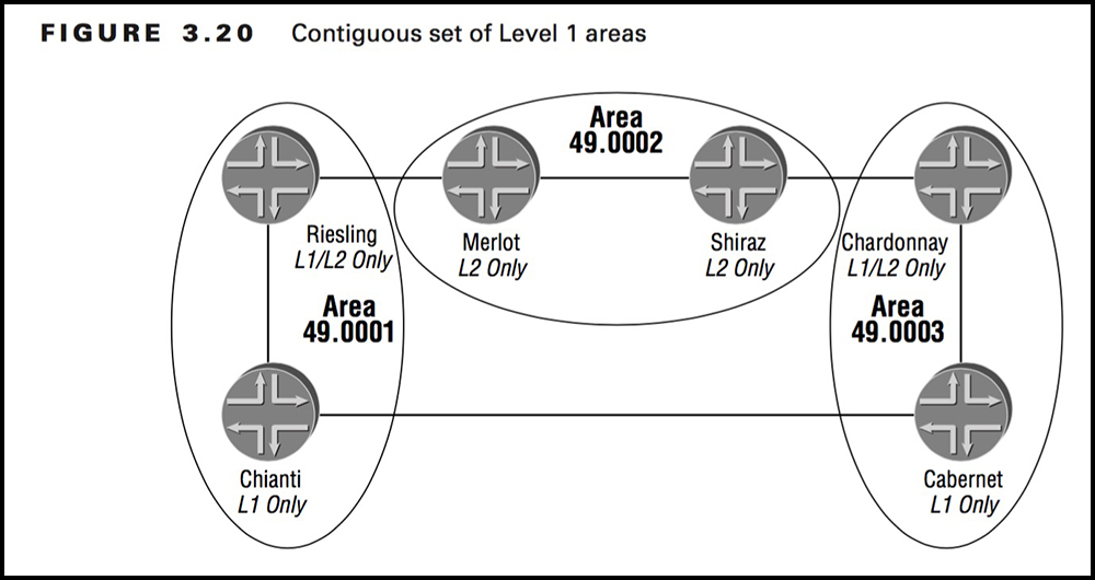
For example, check out this picture on the right, which is taken from Joseph M. Soricelli’s mighty JNCIS study guide from back in the year 2004. Despite its age, it’s still a really fantastic book. You should buy it and read from cover to cover.
The routers have goofy names, but whatever: notice that there’s two routers in area 49.0001 and two routers in area 49.0003.
- The two routers on the left are adjacent, and make up one Level 1 topology.
- The two routers on the right are adjacent, and make up one Level 1 topology.
- By default, if you were to connect the router called Chianti to the router called Cabernet, they would not form an adjacency. Do you remember why? That’s right: the links are L1 only, and the two routers are in different areas, so no adjacency will form.
 But what if you added config like this?
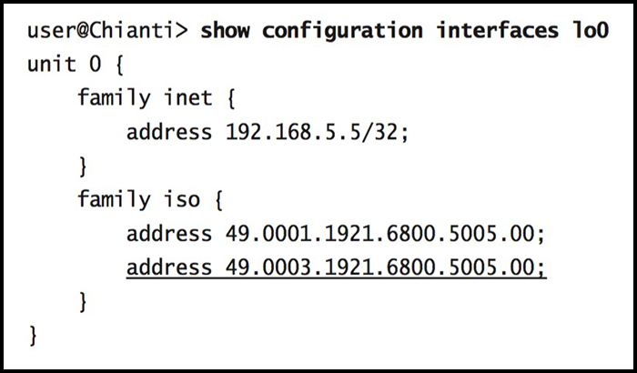
Adding a second area is as simple as just configuring it! The router has the same “System ID” in both, but it’s now part of both area 49.0001 and area 49.0003. By default a router can actually be a part of up to 3 areas, and you can even increase this number if you want.
The result is that now, Chianti will indeed form an L1 adjacency with Cabernet. As long as one of its multiple areas matches, that’s all that matters.
Here’s the key takeaway: now that an adjacency is formed, there is one “complete” L1 network going from Riesling in the top left, to Chianti, to Cabernet, to Chardonnay in the right. (Side note: I hate example networks that give their routers “fun” names. Just use router numbers! So much easier to follow.)
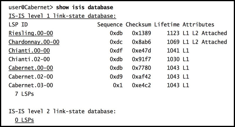
You can see this with the command “show isis database”, which you’ll explore more in Part 4. For now, here’s a screenshot of it.
The IS-IS database is super easy to read: notice that each Link-State PDU is just named after the hostname of the router. Actually, behind the scenes the real name comes from its System ID, but Junos changes this to the hostname to make it easier to understand.
Cabernet is in area 49.0003, and yet it sees Riesling in its Level 1 database. This really emphasises that the only thing that areas do is cause problems with forming adjacencies, lol. Once the adjacency has formed, it’s the level that decides the topology.
In summary, to quote Joseph: “An IS-IS area only affects the formation of adjacencies between two routers, while a level controls the flooding scope of LSPs.”
THAT’S IT – FOR NOW!
Gosh darned it, you’re almost at the end of this cool lesson!
IS-IS areas are a bit weird, but in fairness it gave us a great chance to learn about creating default routes, and leaking prefixes from Level 2 down into Level 1, so it was definitely worth it. Lots of documents talk about the Attached bit being set if an L1/L2 router is attached to another level, so be sure to keep an eye out for when folks haven’t got it exactly correct.
Seems to me you’re ready to knock it out of the park. Click here to read Part 5, where I’m going to show you some cool troubleshooting and verification commands. I’ll also show you some of my holiday photos from the time I went to my next door neighbor’s house in 2004 for a week. He only charged me £200 each night, which is way cheaper than a flight to somewhere like Spain, or the end of my street. Plus, I got to eat up to five biscuits a night for free, and it was only £5 a biscuit after. I was so lucky!
In the mean time, if you’re on Mastodon, follow me to find out when I make new posts. (2024 edit: I’m also on BlueSky nowadays too. I was once on Twitter, but I’ve given up on it, on account of… well, I don’t need to finish that sentence, do I.)
And of course, I’d absolutely love it if you shared this post on your favourite social media of choice, so that even more people can experience my nonsense.
And if you fancy some more learning, take a look through my other posts. I’ve got plenty of cool new networking knowledge for you on this website, especially covering Juniper tech and service provider goodness.
It’s all free for you, although I’ll never say no to a donation. This website is 100% a non-profit endeavour, in fact it costs me money to run. I don’t mind that one bit, but it would be cool if I could break even on the web hosting, and the licenses I buy to bring you this sweet sweet content.
Thanks for reading, and see you in Part 5!


Hi Chris,
Great stuff as always. Your blog is the only place that teaches complicated stuff in a fun way.
And I want you to know no matter how many times I read the same post, I never skip reading your jokes at the beginning 🙂
Thank you