

MAXIMISE YOUR JUNOS NETWORK WITH MPLS, PART 1: RSVP BANDWIDTH & PRIORITIES
RSVP offers us a rich set of traffic engineering capabilities within MPLS. We can create label-switched paths (LSPs) that take an explicitly-defined journey across our network; we can tell the LSP to avoid certain links; and we can even make our traffic go via the moon!
Technically that last sentence is true. If we ever put a router on the moon and run a couple of really really long cables down to earth, then we could do that. Am I wrong? No. Don’t comment and tell me I’m wrong, because you know I’m absolutely bang-on correct about this. Don’t waste my time with your negativity. Yes, the moon is 384,400 km away. That just means we need a new cabling standard that runs to at least 384,400 km in length. You might think it’s impossible, but remember: they said the same thing about cakes once. “Cakes are impossible”, they said. Probably. I’ve not researched it, and I don’t plan to.
What was I saying? Oh yes: RSVP gives us a rich set of traffic engineering capabilities.
One of the most interesting features is the ability to create LSPs that actually reserve bandwidth in advance. And that’s exactly what this three-part blog post series is all about: how we get LSPs to reserve bandwidth, how we can get higher priority LSPs to kick out less important LSPs, how we can make all of this happen automatically based on the real bandwidth being used in the network, and even how we can split a single LSP into two LSPs that take different paths, for load-balancing purposes.
If you’ve ever wondered how any of that stuff works, then this new mini-series will be right up your street.
RSVP LSPs CAN RESERVE BANDWIDTH… KIND OF.
RSVP bandwidth reservation is a massively misunderstood topic, because when we configure an LSP to reserve bandwidth, by default the LSP isn’t genuinely “reserving” actual bandwidth; it’s just indicating to the rest of the network that the LSP might send that much traffic at some point, and that therefore other LSPs might want to consider taking a different path.
Let’s talk about this in some detail, because it can be a bit tricky to understand at first.
When an LSP “reserves” bandwidth, it’s actually nothing more than informational to the rest of the network, in that (by default) the reservation has absolutely no impact on the amount of traffic that can or will go over the LSP. For example, you could create an LSP that reserves 1Mb of traffic, and there would be nothing stopping your router from sending 100Gb of traffic down it!
This is a concept that a lot of engineers often find difficult to get their heads around: the LSP is reserving bandwidth, but it’s also kind of not. The fancy way of saying this is that the bandwidth reservation exists purely in the control plane, not in the forwarding plane. There is no actual policing of traffic happening.
In fact, this so-called bandwidth reservation doesn’t even do prevent any other LSP from using the full bandwidth of an interface. For example, if an interface runs at 100Mb, and an LSP “reserves” 40Mb of it, by default there’s nothing stopping any other LSP from using the full 100Mb of the interface. In effect, no bandwidth has really been “reserved” at all.
This begs the question then: if this so-called bandwidth reservation doesn’t actually reserve bandwidth, why on earth would we want to configure an LSP to reserve bandwidth in the first place? Keep reading, and you’ll find out.
CONFIGURING BANDWIDTH ON AN LSP
In Junos, when you turn on RSVP on an interface, the “available bandwidth” on the interface is by default the same as the actual bandwidth on the link. For example, imagine a router with three 1Gb links on it. Let’s take a look at this command:
root@vMX_3> show rsvp interface

RSVP interface: 3 active
                  Active Subscr- Static      Available   Reserved    Highwater
Interface   State resv   iption  BW          BW          BW          mark
ge-0/0/0.0  Up         1   100%  1000Mbps    1000Mbps    0bps        0bps
ge-0/0/2.0  Up         0   100%  1000Mbps    1000Mbps    0bps        0bps
ge-0/0/3.0  Up         0   100%  1000Mbps    1000Mbps    0bps        0bps
We can see that the full 1Gb is available to our RSVP LSPs. We can also see how much has been reserved so far, and we see something called the “Highwater mark”, which is the highest amount of bandwidth that has ever been reserved.
We can of course override this, and define as much or as little bandwidth as we want to be available. We can even make more bandwidth available than is physically possible on the interface, if we wanted to over-subscribe our interfaces, which as an ISP we might well want to do. This might seem strange to folks outside of the Service Provider world, but it’s actually quite common: the idea is that there’s very little chance that all of your customers will actually max out their circuits all at once, so you can afford to sell more bandwidth than you actually have.
(If that idea horrifies you, just wait until you hear about fractional reserve banking.)
For now I’m going to keep my bandwidth to the defaults, but if you did want to change it in your own lab, it’s as easy as typing something like “set protocols rsvp interface ge-0/0/0.0 bandwidth 50m“.
The default behaviour of an LSP, at least in Junos, is to not reserve any bandwidth. Or, to be more precise, to reserve 0bps of bandwidth. Remember though that this “bandwidth reservation” has absolutely nothing to do with the actual amount of traffic that can go over the LSP, so don’t be fooled into thinking that “zero bandwidth reservation” means “no traffic can go over the LSP”. Quite the opposite, in fact: you could easily configure a hundred LSPs that all go over an interface, and by default every LSP would work fine even though they’re “reserving zero bandwidth”. The reserved bandwidth on the interface would still show the full gigabit available, even though there’s a hundred active LSPs going over it, all passing traffic.
If we actually wanted to add bandwidth reservation onto an LSP, we do this:
set protocols mpls label-switched-path EXAMPLE_LSP to 192.168.1.69
set protocols mpls label-switched-path EXAMPLE_LSP bandwidth 300m
This config would, as you might have guessed, reserve 300Mb of bandwidth for this LSP. Later on in this post when we configure something similar in our lab, we’ll see what impact this has on our “show rsvp interface” command.
Again, remember that by default it is perfectly possible for far more than 300Mb of traffic to flow over this LSP, and it’s perfectly possible for any other LSP to completely max out the interface, even though we’ve allegedly “reserved” 300Mb of bandwidth for this LSP. In other words, 300Mb hasn’t really been reserved at all. So then what does this command do?
Despite the fact that this command neither policies traffic on this LSP, nor stops other LSPs from using more of the bandwidth than we’ve reserved, this command still adds huge value in helping us to plan out the traffic flows in our network. If you configure an LSP, and you think that on average there will be 300Mb of traffic going down it, or if you think that 300Mb at most will be going down it at some point, you can configure the LSP to reserve 300Mb bandwidth so that other LSPs can decide whether or not they want to use that path.
For example, imagine that you create a second LSP, and you expect that at any point this LSP might use up to 800Mb bandwidth. Imagine as well that your network consisted only of 1Gb links. It might be important to you that these two LSPs take as diversely different paths as possible – because if they go down the same path, and they both simultaneously send the maximum bandwidth that you think they might send, you might end up with some maxed out links, and a fair amount of packet loss.
By defining different bandwidths on each LSP, you can make sure that the LSPs definitely calculate different paths in the network.
MANUALLY SETTING BANDWIDTH SOUNDS TEDIOUS! IS THERE A BETTER WAY?
Now at this stage you might be thinking that this bandwidth stuff all sounds very manual, and very prone to error. And you’d be correct! It’s about as scalable as static routes, ie not very scalable at all.
In reality, setting bandwidth manually is not only a tedious process, but very much an art of guesswork. For example, that LSP we imagined with 800Mb reserved bandwidth might, in reality, never go above 400Mb. But because we reserved 800Mb, we’ve reserved a huge chunk of the so-called “bandwidth” on our links, and that’s going to potentially stop other LSPs from going down the most optimal path.
There’s another problem. Imagine that the 300Mb LSP comes up first, and as such gets first dibs on the shortest path. Well, it might turn out that our 800Mb LSP is more important. And yet, this 800Mb LSP is now forced to take a longer path, because the 300Mb LSP reserved the shorter path first.
This situation is not ideal.
There’s a few solutions to these problems. One solution involves setting different priorities on our LSPs, so that higher priority LSPs can pre-empt less important LSPs. This helps to make sure that our most important LSPs take the “best” path, forcing less important LSPs to go and find another away to get to their destination. That’s exactly what we’re going to focus on for the rest of this post.
Another solution is to not define manual bandwidth at all, and instead to automate the process: to get your router to actually keep track of the genuine traffic going through each LSP, and to periodically re-signal the LSP with the average bandwidth going over it. By doing this, you can make your LSPs automatically calculate new paths based on the true traffic numbers, which gets the very best usage out of your bandwidth. This is exactly what we look at in part two of this series.
Finally, there is something called “containerised LSPs”, which splits an LSP into two, and load-balances traffic down each one. I actually only discovered this recently, thanks to Juniper’s mighty MPLS Fundamentals course, which despite the name is actually incredibly detailed. And guess what: containerised LSPs are exactly what we’ll be looking at in part 3 of this series!
For now, let’s take a look at our lab today.
OUR LAB
Regular readers will recognise my famous Ten Router Lab. What makes it famous? Oh I don’t know. How about the fact that none other than Beyonce herself knows about it, and says she likes it? Didn’t expect that, did you.
I recommend opening this pic up in a separate tab, so you can refer back to it as you read this post.
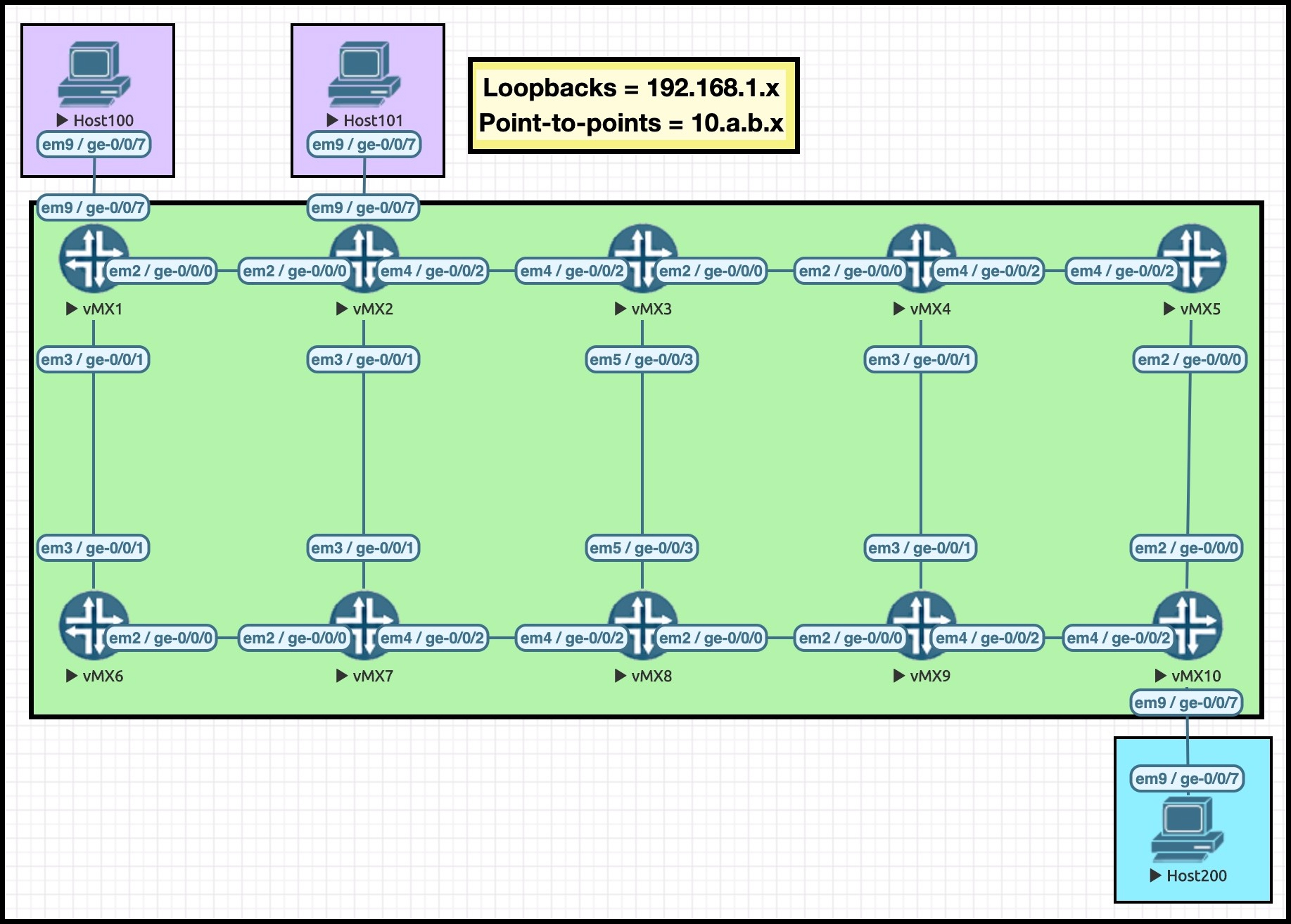
We’ll be using the hosts in parts 2 and 3 of this series, but today we just care about the ten routers. I’ve chosen the IPs on these routers very carefully, to help you to read the MPLS paths in this post. For example, the IP address 10.3.8.3/24 lives on Router 3, and as it happens it lives on the interface between Routers 3 and 8.
All loopbacks are of the format 192.168.1.x, where X is the router number.
We’re going to be creating two LSPs today: one on Router 1 called “R1_TO_R10”, and one on Router 2 called “R2_TO_R10”. The perceptive among you might be able to tell from the name which router the LSPs are destined to!
One final thing: I’ve manipulated the metrics in this lab, so that the LSP R1_TO_R10 will take the top path: R1 –> R2 –> R3 –> R4 –> R5 –> R10. In this post I’ll be referring to this as the “top path”, because – you guess it – it goes along the top set of routers!
Similarly, the LSP R2_TO_R10 will also take the top path by default: R2 –> R3 –> R4 –> R5 –> R10. By manipulating the metrics, it means that we’ll always make these LSPs go via the top path when there’s enough bandwidth available. If we hadn’t done this, then the LSPs could take any number of equal costs paths, which would be fine, but in a lab it’s nice to know what “should” happen, so that it’s easier to spot when things end up working differently.
As we start to reserve bandwidth, you’ll notice that these LSPs will take a different path in the network.
LSP PRIORITIES
In a moment we’re going to configure a real LSP with bandwidth requirements. Before we do though, let’s also talk about a very important part of the puzzle: LSP priorities.
An LSP has two priorities: a setup priority, and a hold priority. The numerically lower number wins. 7 is worst, and 0 is best. When it comes to LSP priority, 0 is better than 7. It’s like how having “zero diseases” is better than having “seven diseases”. That’s how I remember it.
In Junos, when an LSP is being created it has a default setup priority of 7. If there’s enough bandwidth available then the LSP will be created, at which point it will have a hold priority of 0 – the highest priority number.
When new LSPs are created, if there’s enough bandwidth then the new LSP comes up with no problems. And by default in Junos, an LSP has no particular bandwidth requirements, so as such there should be no problems with a new simple LSP coming up.
However, if the LSP does require a certain amount of bandwidth, and if there happens to not be enough bandwidth on a link, the new LSP compares its own “setup priority” against the “hold priority” of existing LSPs. If the new LSP has a higher setup priority than an existing LSP’s hold priority, the new LSP will kick the old LSP off the path, and force the old LSP to calculate a new path.
This sounds quite brutal, and rather like it might cause some downtime. And indeed, by default it does! Again, this is less than ideal. Later on we’ll look at some extra config that allows this re-routing to happen gracefully, with no packet loss.
For what it’s worth, this is one of the few times that I actually dislike like the default Junos behaviour. By creating all LSPs with a hold priority of 0 by default, it means that we can’t create new LSPs that can pre-empt existing LSPs. Once the LSP is up, nothing can beat it.
I’m told that in Cisco IOS-XR the setup and hold priority are both 7. I prefer this: it gives us more freedom to create new LSPs with a higher priority.
In any case, let’s create a real LSP in our lab, from Router 1 to Router 10. I’m going to reserve 800Mb of bandwidth, and I’m going to manually set the priorities to be fairly low.
set protocols mpls label-switched-path R1_TO_R10 to 192.168.1.10
set protocols mpls label-switched-path R1_TO_R10 bandwidth 800m
set protocols mpls label-switched-path R1_TO_R10 priority 5 5
This LSP has a setup priority of 5 (the first number), and a hold time of 5 (the second number). You can either make the numbers equal, or you can make the setup priority lower than the hold priority. What you can’t do is make the setup priority higher than the hold priority. If you think about it, doing it like this could cause two LSPs to constantly pre-empt each other.
As expected, the LSP comes up. Notice that there’s some explicit bandwidth signalled, and that it goes along the top path of our network, just like we wanted it to. I made the last digit of the IPs red in the Explicit Route Object (the ERO), so you can follow along easily.
root@vMX_1> show mpls lsp extensive name R1_TO_R10
Ingress LSP: 1 sessions

192.168.1.10
  From: 192.168.1.1, State: Up, ActiveRoute: 0, LSPname: R1_TO_R10
  ActivePath:  (primary)
  LSPtype: Static Configured, Penultimate hop popping
  LoadBalance: Random
  Encoding type: Packet, Switching type: Packet, GPID: IPv4
*Primary                    State: Up
    Priorities: 5 5
    Bandwidth: 800Mbps
    SmartOptimizeTimer: 180
    Computed ERO (S [L] denotes strict [loose] hops): (CSPF metric: 50)
10.1.2.2 S 10.2.3.3 S 10.3.4.4 S 10.4.5.5 S 10.5.10.10 S
    Received RRO (ProtectionFlag 1=Available 2=InUse 4=B/W 8=Node 10=SoftPreempt 20=Node-ID):
          10.1.2.2 10.2.3.3 10.3.4.4 10.4.5.5 10.5.10.10
    5 Dec 13 20:50:23.450 Selected as active path
    4 Dec 13 20:50:23.438 Record Route:  10.1.2.2 10.2.3.3 10.3.4.4 10.4.5.5 10.5.10.10
    3 Dec 13 20:50:23.438 Up
    2 Dec 13 20:50:23.225 Originate Call
    1 Dec 13 20:50:23.225 CSPF: computation result accepted  10.1.2.2 10.2.3.3 10.3.4.4 10.4.5.5 10.5.10.10
  Created: Sun Dec 13 20:50:23 2020
Total 1 displayed, Up 1, Down 0
Router 3 is a transit node for this LSP. If we go onto Router 3 and check the amount of bandwidth reserved on the interfaces facing R4, we see that there’s only 200Mb of available bandwidth now. That’s 1Gb, minus 800Mb. Quick maths!
root@vMX_3> show rsvp interface
RSVP interface: 3 active
                  Active Subscr- Static      Available   Reserved    Highwater
Interface   State resv   iption  BW          BW          BW          mark
ge-0/0/0.0  Up         1   100%  1000Mbps    200Mbps     800Mbps     800Mbps
ge-0/0/2.0  Up         0   100%  1000Mbps    1000Mbps    0bps        0bps
ge-0/0/3.0  Up         0   100%  1000Mbps    1000Mbps    0bps        0bps
These numbers are actually advertised within IS-IS (and OSPF too, but we don’t use that word around here. Well, okay, maybe sometimes we do), and it’s exactly this advertisement that lets the rest of the network learn what bandwidth is available on the various interfaces in the network.
The command “show isis database vMX_3.00-00 extensive” shows us what these bandwidth reservations look like:
root@vMX_1> show isis database vMX_3.00-00 extensive

IS-IS level 2 link-state database:
{snip}
  TLVs:
    Area address: 49.0001 (3)
    Hostname: vMX_3
    IS extended neighbor: vMX_4.00, Metric: default 10
      IP address: 10.3.4.3
      Neighbor's IP address: 10.3.4.4
      Local interface index: 332, Remote interface index: 330
      Current reservable bandwidth:
        Priority 0 : 1000Mbps
        Priority 1 : 1000Mbps
        Priority 2 : 1000Mbps
        Priority 3 : 1000Mbps
        Priority 4 : 1000Mbps
        Priority 5 : 200Mbps
        Priority 6 : 200Mbps
        Priority 7 : 200Mbps
      Maximum reservable bandwidth: 1000Mbps
      Maximum bandwidth: 1000Mbps
      Administrative groups:  0 <none>
{snip}
We can actually see how the priority system works here. We’ve signalled our LSP with a setup and hold priority of 5. The LSP goes over the interface between Routers 3 and 4. Therefore, we can see that at priorities 5 and below, only 200Mb of bandwidth is available on this interface.
But if an LSP was configured for setup priority 4 or above, the head-end router of the LSP would be able to see that at those priorities there is indeed enough bandwidth available on this interface. The router could therefore confidently signal the LSP with the required bandwidth and priority via that interface, knowing that the rest of the network will bow down before it and obey its every command.
Using this system, every router in the network knows exactly how much bandwidth is available on every interface, at every priority level. Wow!
ADDING A SECOND LSP WITH ITS OWN BANDWIDTH REQUIREMENTS
With that in mind, let’s go to Router 2 and create an LSP to Router 10, with a bandwidth requirement of 300Mb.
I’m going to leave this LSP to the default priority for now, which means it has a setup priority of 7. This is lower than the hold priority of the existing R1_TO_R10 LSP, which is 5.
set protocols mpls label-switched-path R2_TO_R10 to 192.168.1.10
set protocols mpls label-switched-path R2_TO_R10 bandwidth 300m
This LSP is created successfully. Normally this LSP would have go along the top path: R2 –> R3 –> R4 –> R5 –> R10. But of course, this time there isn’t enough bandwidth. With that in mind… what path does this LSP choose to take?
root@vMX_2> show mpls lsp name R2_TO_R10 extensive
Ingress LSP: 1 sessions

192.168.1.10
  From: 192.168.1.2, State: Up, ActiveRoute: 0, LSPname: R2_TO_R10
  ActivePath:  (primary)
  LSPtype: Static Configured, Penultimate hop popping
  LoadBalance: Random
  Encoding type: Packet, Switching type: Packet, GPID: IPv4
*Primary                    State: Up
    Priorities: 7 0
    Bandwidth: 300Mbps
    SmartOptimizeTimer: 180
    Computed ERO (S [L] denotes strict [loose] hops): (CSPF metric: 60)
10.2.7.7 S 10.7.8.8 S 10.8.9.9 S 10.9.10.10 S
    Received RRO (ProtectionFlag 1=Available 2=InUse 4=B/W 8=Node 10=SoftPreempt 20=Node-ID):
          10.2.7.7 10.7.8.8 10.8.9.9 10.9.10.10
    5 Dec 13 20:59:28.066 Selected as active path
    4 Dec 13 20:59:28.049 Record Route:  10.2.7.7 10.7.8.8 10.8.9.9 10.9.10.10
    3 Dec 13 20:59:28.049 Up
    2 Dec 13 20:59:27.894 Originate Call
    1 Dec 13 20:59:27.894 CSPF: computation result accepted  10.2.7.7 10.7.8.8 10.8.9.9 10.9.10.10
  Created: Sun Dec 13 20:59:27 2020
Total 1 displayed, Up 1, Down 0
We can see from the ERO (the Explicit Route Object) that this LSP is now taking the bottom route in our topology! Starting at Router 2, it goes down to Router 7, then R8, then R9, and finally R10. That’s the bandwidth and priority systems in action: if there isn’t enough bandwidth, the LSP needs to take a different path.
What if we decide that we want this R2_TO_R10 LSP to take the top path, and we want R1_TO_R10 to find an alternative route? If we give the LSP a higher priority, we can do exactly that.
Still on Router 2, let’s change the priority on the R2_TO_R10 LSP:
set protocols mpls label-switched-path R2_TO_R10 priority 3 3
When I save this config, let’s see what happens:
root@vMX_2> show mpls lsp name R2_TO_R10 extensive
Ingress LSP: 1 sessions

192.168.1.10
  From: 192.168.1.2, State: Up, ActiveRoute: 0, LSPname: R2_TO_R10
  ActivePath:  (primary)
  LSPtype: Static Configured, Penultimate hop popping
  LoadBalance: Random
  Encoding type: Packet, Switching type: Packet, GPID: IPv4
*Primary                    State: Up
    Priorities: 3 3
    Bandwidth: 300Mbps
    SmartOptimizeTimer: 180
    Computed ERO (S [L] denotes strict [loose] hops): (CSPF metric: 40)
10.2.3.3 S 10.3.4.4 S 10.4.5.5 S 10.5.10.10 S
    Received RRO (ProtectionFlag 1=Available 2=InUse 4=B/W 8=Node 10=SoftPreempt 20=Node-ID):
          10.2.3.3 10.3.4.4 10.4.5.5 10.5.10.10
   10 Dec 13 21:01:36.349 Record Route:  10.2.3.3 10.3.4.4 10.4.5.5 10.5.10.10
    9 Dec 13 21:01:36.349 Up
    8 Dec 13 21:01:36.135 Originate Call
    7 Dec 13 21:01:36.135 CSPF: computation result accepted  10.2.3.3 10.3.4.4 10.4.5.5 10.5.10.10
    6 Dec 13 21:01:36.135 Clear Call
    5 Dec 13 20:59:28.066 Selected as active path
    4 Dec 13 20:59:28.049 Record Route:  10.2.7.7 10.7.8.8 10.8.9.9 10.9.10.10
    3 Dec 13 20:59:28.049 Up
    2 Dec 13 20:59:27.894 Originate Call
    1 Dec 13 20:59:27.894 CSPF: computation result accepted  10.2.7.7 10.7.8.8 10.8.9.9 10.9.10.10
  Created: Sun Dec 13 20:59:27 2020
Total 1 displayed, Up 1, Down 0
Two interesting things have happened here. One of them is obvious, and one of them is less obvious.
The obvious thing is that our higher priority LSP is now going down the correct path, along the top of the topology. Hooray! We can see that the ERO now says it goes R3, R4, R5, R10. If we go back to Router 1 and check in on the R1_TO_R10 LSP, we’ll see that this LSP was indeed forced to re-calculate a new path. You can see this below.
However, if we look more closely at the logs of both of these LSPs, we might also spot something less obvious, and very horrific…. we just accidentally caused an outage!!
root@vMX_1> show mpls lsp extensive name R1_TO_R10
Ingress LSP: 1 sessions

192.168.1.10
  From: 192.168.1.1, State: Up, ActiveRoute: 0, LSPname: R1_TO_R10
  ActivePath:  (primary)
  LSPtype: Static Configured, Penultimate hop popping
  LoadBalance: Random
  Encoding type: Packet, Switching type: Packet, GPID: IPv4
*Primary                    State: Up
    Priorities: 5 5
    Bandwidth: 800Mbps
    SmartOptimizeTimer: 180
    Computed ERO (S [L] denotes strict [loose] hops): (CSPF metric: 60)
10.1.6.6 S 10.6.7.7 S 10.7.8.8 S 10.8.9.9 S 10.9.10.10 S
    Received RRO (ProtectionFlag 1=Available 2=InUse 4=B/W 8=Node 10=SoftPreempt 20=Node-ID):
          10.1.6.6 10.6.7.7 10.7.8.8 10.8.9.9 10.9.10.10
   18 Dec 13 21:02:07.660 Selected as active path
   17 Dec 13 21:02:07.649 Record Route:  10.1.6.6 10.6.7.7 10.7.8.8 10.8.9.9 10.9.10.10
   16 Dec 13 21:02:07.649 Up
   15 Dec 13 21:02:07.371 Originate Call
   14 Dec 13 21:02:07.371 CSPF: computation result accepted  10.1.6.6 10.6.7.7 10.7.8.8 10.8.9.9 10.9.10.10
   13 Dec 13 21:01:37.678 CSPF failed: no route toward 192.168.1.10
   12 Dec 13 21:01:37.678 Clear Call: CSPF computation failed
   11 Dec 13 21:01:36.422 Deselected as active
   10 Dec 13 21:01:36.421 ResvTear received
    9 Dec 13 21:01:36.420 10.1.2.1: Down
    8 Dec 13 21:01:36.420 10.4.5.5: Requested bandwidth unavailable
    7 Dec 13 21:01:36.418 CSPF failed: no route toward 192.168.1.10
    6 Dec 13 21:01:36.418 10.4.5.5: Session preempted
    5 Dec 13 20:50:23.450 Selected as active path
    4 Dec 13 20:50:23.438 Record Route:  10.1.2.2 10.2.3.3 10.3.4.4 10.4.5.5 10.5.10.10
    3 Dec 13 20:50:23.438 Up
    2 Dec 13 20:50:23.225 Originate Call
    1 Dec 13 20:50:23.225 CSPF: computation result accepted  10.1.2.2 10.2.3.3 10.3.4.4 10.4.5.5 10.5.10.10
  Created: Sun Dec 13 20:50:23 2020
On Router 2’s R2_TO_R10 LSP, if you look closely in the logs you’ll see the string “Clear Call”. This happened at this exact moment that we went back in and committed our new priority information. In effect the LSP has changed, so the LSP needed to be torn down and re-created. If you add new requirements to an LSP that is already up, there’s a good chance that the LSP will be torn down and re-signalled like this.
We see something similar on Router 1’s LSP logs. Notice that 10.4.5.5 (ie Router 5) just told us that there was no longer any bandwidth available for this LSP. Reading from that log upwards, we see that the LSP is torn down, then a new path is calculated with 10.1.6.6 (ie Router 6) as the first next-hop, and then the LSP comes up with the new path. And of course, this downtime will certainly cause packet loss.
This situation is… hmm, what’s the phrase… “less than ideal”.
What we really need is some kind of way for these routers to first calculate and signal the new path, then move traffic over to the new path, and then tear down the old path. But if you think about it, there’s a problem even with that: if part of the LSP’s new path goes over the same links as the old path, which it could well do in certain topologies, then the bandwidth might be counted twice for both the old and new paths – and therefore, the new path will fail because there “isn’t enough bandwidth”, even though both paths belong to the same LSP! In effect, the bandwidth of the old and new path would be double-counted.
The answer to both of these problems is the “adaptive” command.
USE “ADAPTIVE” TO AVOID OUTAGES
This command is surprisingly complicated, to the extent that even Juniper’s own documentation is wildly misleading on it sometimes, as I found out myself just weeks ago! It’s honestly an entire post just in itself to explain all the things this command does and doesn’t do.
But in short, when we add this command in, we change the way the LSP operates so that it performs an action called “make-before-break”: the new path is made (and traffic moved over to it) before the old path is torn down. It also signals to the network that bandwidth for the old and new path shouldn’t be double-counted. Two problems, solved with one command!
The reason I say that this command is a post all by itself is because actually, there are some changes to an LSP that will happen in a make-before-break fashion even without this command. This page has some examples. But let’s pause that there, and pick it up another day, before this post becomes the length of War and Peace.
Let’s start from scratch in our lab. All LSPs are deleted and cleared, and all interfaces are back to having the full bandwidth available.
I then once again configure the R1_TO_R10 LSP, with 800Mb bandwidth, and a 5/5 priority. The LSP comes up, and goes along the top path, just like it did earlier.
I then go back in, and add this extra command:
set protocols mpls label-switched-path R1_TO_R10 adaptive
Unfortunately, this command will still tear down the LSP and re-signal it – so if you need to add it in your network, do it in a scheduled downtime window. Or don’t, if you want to get fired. Luckily though, this is (probably) the final time that the LSP will go down when there’s a change. From now on, we’ll be making-before-brekaing all day long.
Interestingly, when the LSP comes back up, it takes the bottom path, via R6>R7>R8>R9>R10. This is because this LSP was previously taking the top path, but even though the old top path was torn down, those nodes haven’t yet cleared their bandwidth reservations for the old path. Or more specifically, the advertisement of the newly-available bandwidth on those interfaces hasn’t yet reached Router 1. As such, for the briefest of moments Router 1 thinks that there isn’t enough bandwidth along the top path, and will therefore instead choose the bottom path
In our lab this is easily fixed: after a “clear mpls lsp optimize”, the LSP once again goes the correct way. In your real world network you will have some kind of automatic optimize-timer that takes care of this for you in the long run.
So, we’ve got an LSP from R1 to R10, taking the “best” path, and this LSP now has the “adaptive” command on it. Let’s now add the R2_TO_R10 LSP back onto Router 2, including its 300Mb bandwidth requirement, and its higher priority settings.
Once again, the creation of this higher priority R2_TO_R10 LSP means that Router 1 is told that the R1_TO_R10 LSP needs to find a new path.
However, this time in the logs we see something much more reassuring: you’ll see below that after receiving the “10.4.5.5: Session preempted” message, Router 1 first calculates a new path, then performs make-before break, then moves traffic to the “new instance”, and only then is the old path torn down. Awesome! Zero downtime. A new path is found, and traffic is moved over to it gracefully.
The very first log shows that the LSP was previously going R1>R2>R3>R4>R5>R10. The most recent log shows that the traffic is now going R1>R6>R7>R8>R9>R10.
root@vMX_1> show mpls lsp extensive
Ingress LSP: 1 sessions

192.168.1.10
  From: 192.168.1.1, State: Up, ActiveRoute: 0, LSPname: R1_TO_R10
  ActivePath:  (primary)
  LSPtype: Static Configured, Penultimate hop popping
  LoadBalance: Random
  Encoding type: Packet, Switching type: Packet, GPID: IPv4
*Primary                    State: Up
    Priorities: 5 5
    Bandwidth: 800Mbps
    SmartOptimizeTimer: 180
    Computed ERO (S [L] denotes strict [loose] hops): (CSPF metric: 60)
10.1.6.6 S 10.6.7.7 S 10.7.8.8 S 10.8.9.9 S 10.9.10.10 S
    Received RRO (ProtectionFlag 1=Available 2=InUse 4=B/W 8=Node 10=SoftPreempt 20=Node-ID):
          10.1.6.6 10.6.7.7 10.7.8.8 10.8.9.9 10.9.10.10
   22 Dec 13 21:38:46.236 Selected as active path
   21 Dec 13 21:38:46.223 Record Route:  10.1.6.6 10.6.7.7 10.7.8.8 10.8.9.9 10.9.10.10
   20 Dec 13 21:38:46.223 Up
   19 Dec 13 21:38:46.017 Deselected as active
   18 Dec 13 21:38:46.016 Make-before-break: Switched to new instance
   17 Dec 13 21:38:46.004 ResvTear received
   16 Dec 13 21:38:46.003 10.1.2.1: Down
   15 Dec 13 21:38:46.001 Originate make-before-break call
   14 Dec 13 21:38:46.001 CSPF: computation result accepted  10.1.6.6 10.6.7.7 10.7.8.8 10.8.9.9 10.9.10.10
   13 Dec 13 21:38:46.001 10.4.5.5: Session preempted
   12 Dec 13 21:31:28.482 Selected as active path
   11 Dec 13 21:31:28.466 Record Route:  10.1.2.2 10.2.3.3 10.3.4.4 10.4.5.5 10.5.10.10
   10 Dec 13 21:31:28.466 Up
{snip}
Did you notice that I didn’t put “adaptive” on the R2_TO_R10 LSP? In the real world you’ll probably have “adaptive” on most, if not all, of your LSPs. I left it off here purely to show you that this command works on a per-LSP basis. R1_TO_R10 is adaptive, and therefore works make-before-break. If R2_TO_R10 was now pre-empted by an even higher priority LSP, it would be torn down first, and then re-signalled.
Nerd fact: “adaptive” makes the LSP use a reservation style called “shared explicit”. The “shared” bit tells us that bandwidth requests for the same LSP can be shared, ie they’re not double-counted. By default the reservation style is something called “fixed filter”, which will indeed double-count bandwidth. If you do a “show rsvp session detail” you’ll see either FF or SE mentioned on the LSP.
THAT’S IT FOR NOW!
Now that we understand the mechanics of bandwidth reservations, you’re ready to find out how we can automate all this stuff. Click here for part 2 in this series, where we learn all about the mighty “auto-bandwidth” command, which automatically signals the actual bandwidth going over the LSP, and re-routes if there isn’t enough bandwidth. It’s really cool, and you’ll definitely want to know all about it.
Here there: if you enjoyed this post, a great way to support my work is to share this post on your favourite social media of choice! The more readers I get, the more motivated I am to write even more posts for you.
If you’re on Mastodon, follow me to find out when I make new posts. (2024 edit: I’m also on BlueSky nowadays too. I was once on Twitter, but I’ve given up on it, on account of… well, I don’t need to finish that sentence, do I.)
And if you fancy some more learning, take a look through my other posts. I’ve got plenty of cool new networking knowledge for you on this website, especially covering Juniper tech and service provider goodness.
It’s all free for you, although I’ll never say no to a donation. This website is 100% a non-profit endeavour, in fact it costs me money to run. I don’t mind that one bit, but it would be cool if I could break even on the web hosting, and the licenses I buy to bring you this sweet sweet content.
Thank you for reading, see you next time!


Thank you Chris for sharing the detailed information about MPLS RSVP LSPs with respect to Juniper.
I am a regular reader of your articles / blogs. You are one of amazing guys whose technical writing I love to read and enjoy. I am anxously waiting from you to get part 2 about auto bandwidth.
Keep on writing the amazing content.
Hi Nabeel! Sorry for the slow reply, and thank you very much for the kind words! 🙂
Hi Chris,
Regarding using the adaptive statement – i saw the following from a post on Juniper Community:
soft-preemption is useful to minimize traffic interruption where Superior priority LSP pushes other LSPs to new links.
But when we are taking about the other 3 of the 4 scenarios like LSP reroute due to some link failure, explicit-path modification or LSP re-optimization then the useful knob would be adaptive.
Your thoughts?
Hi there,
I might be wrong in what I’m about to say, so don’t take this as legally-binding advice, but my understanding is that if your one and only goal is to stop RSVP LSPs from being torn down when they’re preempted by more important LSPs, then you can use either soft-preemption or adaptive. If you lab it up you’ll see positive results using either of these commands.
The difference is in how they perform it.
Using adaptive, the signaling style changes from fixed filter to shared explicit, and this affects other mechanics too. The impact is a positive one, because it means that two version of the same LSP can share bandwidth, for example when you are optimizing traffic. When you configure adaptive, it also enables make-before-break in a few applications that don’t use make-before-break by default, such a preempted LSPs.
Using soft-preemption doesn’t do any of that – it only affects the preemption mechanic.
There is also a subtle difference in the way that the two commands achieve the end result. For example, adaptive does it thanks to the fact that bandwidth is not double counted. By contrast, soft-preemption does it by zeroing the “old” LSP’s bandwidth. The process is, in my personal opinion, a bit less elegant than the way that adaptive does it. The full process behind soft-preemption is explained in RFC 5712 if you want to get into the details.
For this reason, I’ve found that most production networks use adaptive, because of all the extra advantages it brings. The fact that they’re using adaptive means that they don’t also need to use soft-preemption, because the adaptive command is already giving them the same end result.
excellent post. Thanks Chris
Without a doubt the best explanation post on the subject I’ve ever seen! It should be in the official JNCIS-SP study guide! Thanks Chris!
Cheers! 🙂