
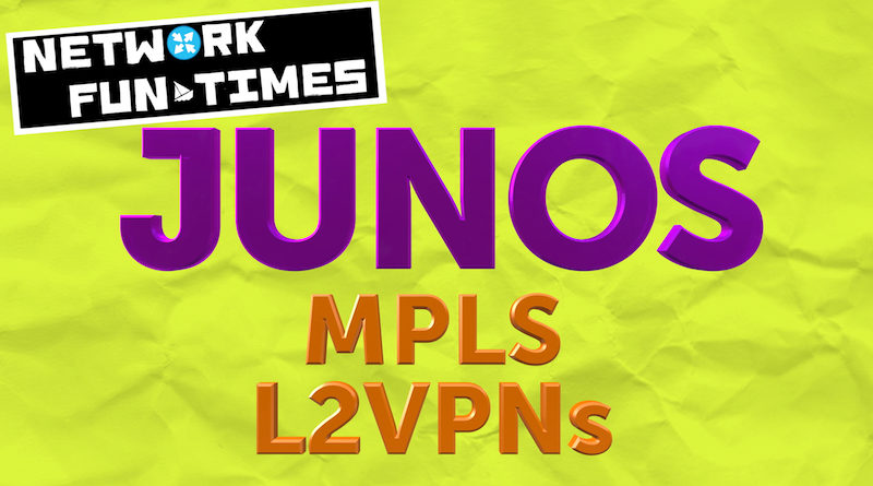
L2VPN: THE LABEL BASE AND OFFSET, EXPLAINED!
If you’re studying an advanced networking Service Provider cert, like Juniper’s JNCIP-SP, then at some point you’ll get into the nitty-gritty of the control plane side of pseudowires.
First you’ll learn that there’s two different ways of creating a pseudowire: BGP-signalled (aka Kompella pseudowires, AKA “Layer 2 VPNs” in Juniper parlance), and LDP-signalled (aka Martini pseudowires, aka “Layer 2 Circuits” in Juniper parlance).
You’ll then learn that there are other kinds of pseudowires that don’t exist, which I’ve made up. For example, you can create a pseudowire by shouting your files really loudly into a tin can, then sealing the can, then throwing the can into the sea. When someone over the other side of the world finds the can and opens it, they will hear your message, and the virtual link is complete. (This does involve you being able to speak Microsoft Word as a second language, and TCP/IP as a third.) This kind of pseudowire – which remember, doesn’t exist, I’m lying to you here, I’m lying to your face – is ratified in RFC????, which the first RFC to be referred to by emojis.
Anyway, forget I said any of that. You saw nothing, you heard nothing.
A unique thing about BGP-signalled L2VPNs is the way that the VPN labels are advertised. You’ll read about something called the “label base”, and something called a label block offset. If you’re good at math then you probably find it a breeze to understand. I, however, am not good at math. In fact, I am bad at math. Exhibits A: my bank balance. Exhibit B: my pension. Exhibit C: the overwhelming number of memes I carry with me at all times, “just in case I need them”.
Well, if you’re not good at the ol’ numbers either, then this post is for you. We’ll not only explain what these words mean, but we’ll explain why we care. We’re going to use Juniper config today, but the behaviour of the protocol is the same across all vendors. So sit back and enjoy the ride, as we learn how L2VPN-style pseudowires work behind the scenes!
A QUICK REFRESHER: WHAT IS A PSEUDOWIRE?
A pseudowire connects together two, and only two, interfaces together – on different routers. Anything that comes in on one interface is MPLS-switched across the provider network, and sent out of the interface at the other end.
In that respect, a pseudowire is, as the name implies, a pseudo-wire, a virtual cable that we can imagine running right across our service provider network. The end result should be exactly the same as if we’d run many metres/kilometres of cable between the two PEs. Swap in your own preferred unit of measurement there if you like. Feet, miles, horse-faces: whatever makes you happy.
It’s important to understand that if one physical interface has lots of logical sub-interfaces, then its the sub-interface that has its own pseudowire to another (logical) interface in the PE network. For example, imagine a physical interface on PE-A has ten sub-interfaces. If there were lots of other PEs in our network, then on PE-A we could:
- Take logical interface ge-0/0/0.1 on PE-A, and create a pseudowire to a logical interface on PE-B
- Take logical interface ge-0/0/0.2 on PE-A, and create a pseudowire to a logical interface on PE-C
- Take logical interface ge-0/0/0.3 on PE-A, and create a pseudowire to a logical interface on PE-D
- And so on.
That might seem obvious, but it will be important later on.
The above is true whether it’s L2VPN (BGP-signalled) or L2circuit (LDP-signalled). The signalling doesn’t matter: the functional result from the customer point-of-view is exactly the same.
By the way, don’t be confused: although the phrases L2VPN and L2Circuit have very specific meanings within the Juniper ecosystem, be aware that it is also extremely common for network engineers to use either of those two terms interchangeably, to describe the concept of pseudowires as a whole. Which is obviously great and fantastic, and definitely introduces no problems or confusion in conversations.
You can then bring in the fact that Cisco calls them Xconnects, which gets maddeningly confusing when you hear people talking about running a cross-connect in the data centre, and it turns out they mean a physical cable, not a pseudowire. Still, I’m sure these various confusions keep plenty of people gainfully employed.
A QUICK REFRESHER: WHAT ARE VPN LABELS?
In MPLS VPNs, a PE assigns a VPN label to identify which VPN the incoming traffic belongs to. For example, PE-A might tell PE-B “If you want to send traffic to me belonging to this pseudowire, tag it with label 123456. This will tell me to send the traffic out of the interface belonging to this VPN.”
Now, bearing in mind that a pseudowire connects two and only two interfaces together, let me ask you a question: if you were designing this protocol yourself, how would you write an RFC that explains how labels should be advertised? I had a think about this, and I expect I’d describe it as something like this:
“Each PE assigns a local VPN label to this pseudowire, and advertises it to the remote PE. The process for choosing which label to use is left up to the router vendor. When the remote PE receives this label advertisement, the remote PE will know to add that label to any traffic it sends down the pseudowire”.
Simple, right? And indeed, if we were talking about LDP-signalled pseudowires, that’s essentially how it works. Section 5 of the RFC for LDP pseudowires describes the process, but it’s pretty much as easy as that.
However, BGP-signalled pseudowires don’t do it like this at all.
Basically, instead of advertising one single label, BGP pseudowires advertise a range of labels via a “label block”, along with a few extra bits of information that allow the remote PE to work the label out itself. This is very confusing to new students, because they often ask: why on earth would you need a range of labels in a pseudowire? There’s only one place the traffic is going to!
It turns out though that there’s a few advantages to this method.
First, it allows us to configure lots of pseudowires that all come in to one site, but advertise just one label block for all of them. This lets us send one single BGP advertisement for all of the pseudowires that we’ve pre-provisioned. Much easier on the advertisements! We’ll see this in action later on.
Second, the signalling used for L2VPN is exactly the same as the signalling for BGP VPLS. We’ll see this later on too.
Imagine PE-A was in a VPLS with PE-B, PE-C, PE-D and PE-E. In this situation, PE-A could once again send one single advertisement containing a block of VPN labels, which the other PEs could then use to work out which label to use.
This method is much more efficient than sending four advertisements to all four remote routers, and then getting those four routers to process those four updates and discard three of them. Scale it out to dozen of sites for hundreds of customers, and it becomes clear why sending fewer advertisements is an advantage.
THIS SOUNDS VERY THEORETICAL. WHY DO I NEED TO KNOW THIS?
Now at this point, you might be wondering why you should care about this. For most engineers, the process of how the labels are advertised isn’t really important. The only people who should need to know that are the people who write the code that powers your vendor OS of choice.
But actually, there’s a really good reason to know about it: we’re going to see in this post that there are certain bits of configuration that directly relate to how the labels are generated – and if you’re stuck getting your pseudowire to come up, then understanding what’s happening behind the scenes can make you a lot more successful in bringing your L2VPN up on your first go.
With that in mind, we’re going to configure some L2VPNs today, and we’ll pay particular attention to the control plane goodness. First though, let’s take a moment to understand our topology today. I’d strongly recommend opening up the pic below in a new tab to see it properly, and to easily refer back to it as you read this post.
LET’S LOOK AT MY LAB TODAY!
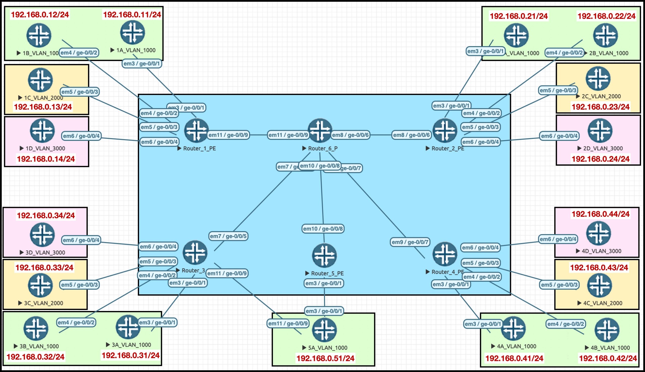 Wowzeroonie, that looks like a big lab!! But don’t worry: if you look at one corner, you’ll see it’s exactly the same as the other three corners. In other words, it looks complicated at first, but it’s actually super simple.
The blue box in the middle is my ISP core network of six routers. Gosh, aren’t they handsome? PE6 is our route reflector, which makes it extra handsome. Very brave, very respectable. Perhaps you want to marry it? I don’t blame you. Sadly, it’s married already, so stop dreaming.
PE1, PE2, PE3 and PE4 each have four CE (customer edge) routers connected to them. Notice how the colour of the boxes represents the VLAN tag on the WAN interface::
- Two of them are in VLAN1000 (green)
- One of them is in VLAN2000 (yellow)
- One of them is in VLAN3000 (red)
The CE routers are configured with IPs, but for today’s lab you don’t need to worry about that. So why did I put them on the map? Because in a future post we’ll change this lab to be a VPLS VPN, and we’ll have fun playing with VLAN tag manipulation. Oh boy do I know how to party! If that sounds like something you’d like to know about, keep an eye on Twitter for when I make new posts.
Okay, I think we’re ready to make our first pseudowire. If you like, we could hold hands as we do it? No? Okay, fair enough.
LET’S CREATE A SIMPLE L2VPN BETWEEN PE1 AND PE2
Below is the config for an L2VPN between the CE called “1C_VLAN_2000” (connected to ge-0/0/3.2000 on PE1), and the CE called “2C_VLAN_2000” (ge-0/0/3.2000 on PE-2).
To keep it easy, this lab is going to connect CE routers together which share a common VLAN tag, but be aware that this certainly isn’t mandatory: with a bit of extra configuration, we could easily swap the VLAN tags at either end as they enter or leave the PE.
First of all, we’ll configure ge-0/0/3.2000, the interface on PE-1 that’s facing the CE:
set interfaces ge-0/0/3 flexible-vlan-tagging
set interfaces ge-0/0/3 encapsulation flexible-ethernet-services
set interfaces ge-0/0/3 unit 2000 encapsulation vlan-ccc
set interfaces ge-0/0/3 unit 2000 vlan-id 2000
On MX routers I’m very inclined to just use “flexible-vlan-tagging” and “encapsulation flexible-ethernet-services” everywhere. So much easier. The combination of these two commands lets you have untagged, single tagged, and dual-tagged traffic all on one interface, and lets you have multiple address families on one interface, be they layer 3 or layer 2.
Notice that the encapsulation is “vlan-ccc”. This means that the traffic is VLAN tagged. This is as opposed to “ethernet-ccc” where the VLAN is considered part of the payload, and therefore the pseudowire will be carrying lots of different VLANs.
(Although, to be precise, it is possible for an interface with vlan-ccc encapsulation to also carry multiple VLANs, using the “vlan-id-list” command. The main thing to take away is that in ethernet-ccc encapsulation, the VLAN tag is just part of the payload, whereas in vlan-ccc the VLAN tag is analysed to decide which pseudowire the traffic belongs to. Thanks to my pal Matt Dinham for pointing that out!)
“CCC” stands for Circuit Cross-Connect. It’s a very old and very legacy Juniper proprietary method of doing pseudowires. For reasons that I’ve never fully understood, the encapsulation method carries over to other pseudowire methods, like it does here.
The equivalent config exists on the interface on PE-2 as well.
Next, we make an L2VPN like this:
root@Router_1_PE> show configuration routing-instances
L2VPN_BETWEEN_1C_AND_2C {
    instance-type l2vpn;
    interface ge-0/0/3.2000;
    route-distinguisher 1.1.1.1:999;
    vrf-target target:64512:999;
    protocols {
        l2vpn {
            encapsulation-type ethernet-vlan;
            site A {
                site-identifier 1;
                interface ge-0/0/3.2000;
}}}}
If you’ve not seen an L2VPN before, you might still recognise a lot of this config from L3VPNs. For example, we set a route target and a route distinguisher. When you remember that both L2VPN and L3VPN are advertised via BGP, it makes sense that we’d have these elements in the config. We’re also defining this as an instance-type of “l2vpn”, and we’re putting the relevant interface into this routing-instance.
(It’s worth mentioning here that in Junos, a BGP-signalled L2VPN is created as a routing-instance, whereas an LDP-signalled L2circuit is configured under “protocols l2circuit”.)
In the config above, notice that this is “Site A”. The “A” is just some text; we could have called it whatever we like. Within the site, we’re choosing a site-identifier of 1. That will be important in a moment.
I put exactly the same config onto PE-2, apart from using a different route-distinguisher, and setting the site-identifier to 2. The site is called Site B in that config.
Notice above that I didn’t configure what the remote site ID is. That’s okay: there’s a default behaviour that means this VPN will still come up. If you don’t actually set the remote-site-id, here’s how it works: it starts at 1, and goes up by 1 in the order that the interfaces are listed in the config. Unless you yourself are site 1 of course, in which case the remote-site-id starts at 2. And that’s what’s happening here: we are site 1, so the counting starts at 2.
“Now wait a second”, you might be thinking after reading that paragraph. “The order that the interfaces are listed in? I thought this was a pseudowire? Surely there’s only one interface?”
Good question, Harry! Keep that in mind, and we’ll come back to it.
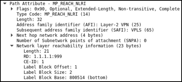 The result of our config is a BGP advertisement that looks something like this.
Notice that it’s Address Family Indicator 25 (Layer 2 VPN), but interestingly it’s Sub-AFI 65 (VPLS). This isn’t really a VPLS, but this screenshot shows that the signalling between VPLS and L2VPN is indeed the same!
We also see the route distinguisher the CE-ID (aka the Site ID), the label block base, the block size, and the block offset. There is a route-target too, but it’s not shown in this screenshot
All of this information will be used by the PE at the other end. Let’s find out how.
CHECKING IF OUR L2VPN WORKS
You can see below that the “show l2vpn connections” command gives you tons of codes which help you to troubleshoot why the VPN isn’t coming up.
Fun story: I know of one UK-based ISP who actually use these codes as a question in the technical interview for new staff. They’ll give them a code and ask them what it means off the top of their head, expecting them to have all the codes memorised. My response to that would be: if your L2VPNs are going wrong so often that you’ve had to memorise these error codes, you’re doing something seriously wrong as an organisation.
Anyway: I’ll filter these codes out of the rest of my CLI output, to keep things lean.
Below these codes, you see the actual info we’re after: the line that starts “Instance: L2VPN_BETWEEN_1C_AND_2C” is where it all kicks off. Take a look at the bits I’ve marked in red. Once you’ve read that, I’ll explain what’s going on.
root@Router_1_PE> show l2vpn connections extensive
Layer-2 VPN connections:
Legend for connection status (St)
EI -- encapsulation invalid      NC -- interface encapsulation not CCC/TCC/VPLS
EM -- encapsulation mismatch     WE -- interface and instance encaps not same
VC-Dn -- Virtual circuit down    NP -- interface hardware not present
CM -- control-word mismatch      -> -- only outbound connection is up
CN -- circuit not provisioned    <- -- only inbound connection is up
OR -- out of range               Up -- operational
OL -- no outgoing label          Dn -- down
LD -- local site signaled down   CF -- call admission control failure
RD -- remote site signaled down  SC -- local and remote site ID collision
LN -- local site not designated  LM -- local site ID not minimum designated
RN -- remote site not designated RM -- remote site ID not minimum designated
XX -- unknown connection status  IL -- no incoming label
MM -- MTU mismatch               MI -- Mesh-Group ID not available
BK -- Backup connection         ST -- Standby connection
PF -- Profile parse failure      PB -- Profile busy
RS -- remote site standby SN -- Static Neighbor
LB -- Local site not best-site   RB -- Remote site not best-site
VM -- VLAN ID mismatch
Legend for interface status
Up -- operational
Dn -- down
Instance: L2VPN_BETWEEN_1C_AND_2C
  Local site: A (1)
    Number of local interfaces: 1
    Number of local interfaces up: 1
    ge-0/0/3.2000       2
    Label-base        Offset     Size  Range     Preference
    800514            1          2      2         100
      status-vector:  0
    connection-site           Type  St     Time last up          # Up trans
    2                         rmt   Up     Jan 17 13:18:04 2021           1
      Remote PE: 2.2.2.2, Negotiated control-word: Yes (Null)
      Incoming label: 800515, Outgoing label: 800014
      Local interface: ge-0/0/3.2000, Status: Up, Encapsulation: VLAN
{snip}
Some of the stuff here is self-explanatory: we see the remote PE’s IP address, we see the fact that it’s “up”, we see the date/time it came up, and we see the local and remote site IDs that we configured. The number under “connection-site” is actually what’s being advertised by the other end. In other words, PE-2 is telling us that it’s connected to Site 2.
We also see the incoming label, and the outgoing label. On PE-1, we see that any traffic with the label 800515 has come from PE-2, is destined for this VPN, and therefore should go out of local interface ge-0/0/3.2000.
What’s less obvious is the “label base”. And indeed, it’s not very obvious what the other numbers mean either: the Offset, the Site, the Range. What’s going on there?
Before I explain it, this is the equivalent output on PE-2:
root@Router_2_PE> show l2vpn connections extensive | find L2VPN_BETWEEN_1C_AND_2C
Instance: L2VPN_BETWEEN_1C_AND_2C
  Local site: B (2)
    Number of local interfaces: 1
    Number of local interfaces up: 1
    ge-0/0/3.2000       1
    Label-base        Offset     Size  Range     Preference
    800014            1          2      1         100
      status-vector:  0
    connection-site           Type  St     Time last up          # Up trans
    1                         rmt   Up     Jan 17 13:18:03 2021           1
      Remote PE: 1.1.1.1, Negotiated control-word: Yes (Null)
      Incoming label: 800014, Outgoing label: 800515
{snip}
(By the way, don’t be fooled by the fact that the two labels are relatively close to each other: “800014” and “800515”. That’s just because this is a really small lab, and both boxes start working out labels from the same starting point. A lot of times you’ll find in Junos that the labels start at 800000, and go up from there as new LSPs and VPNs are created.)
THE LABEL BASE, AND THE OFFSET
Instead of a PE advertising one single label to represent the pseudowire, what happens is this: a starting label is advertised, and then some extra information is included which indicates how big the range is, allowing the receiving PE to calculate which label it should use depending on its site ID.
At first, I found this confusing. Why advertise a range of labels when it’s just a pseudowire? It’s not like we have a range of sites. After all, a pseudowire connects two, and only two, interfaces together.
And indeed it does. But here’s an idea: what if our Site 1 was a hub site for a hub-and-spoke VPN? You could imagine a situation where a customer comes to you and says “we’re going to bring a hundred spoke sites online over the next year, and we want each site to have an L2VPN directly to the hub site. We’ll take care of the routing between sites: we just need layer 2 services from you.”
Chances are that the PE’s connection to the hub site would be one single physical WAN link, sub-interfaced a hundred times to allow you to create a hundred separate pseudowires to the hundred spoke sites.
But how would you actually configure this on the PE? Creating a hundred individual routing-instances seems like a lot of configuration, not to mention the fact that you need to send a hundred BGP updates for each sub-interface.
That’s where the label base comes in.
Instead of configuring a hundred routing-instances, you can in fact put all the interfaces into one single routing-instance. All hundred interfaces would belong to Site 1, but what you could also do is assign each sub-interface its own remote-site-ID in advance, so that all the sites were pre-provisioned. This gets half the job done all in one hit, giving you the freedom to configure the other sites whenever you like.
If you do this, something interesting happens: rather than send a hundred individual label advertisements, the PE router can instead bundle them all up into one single advertisement, with a much larger “label base”. The remote PEs receive this advertisement – and using a little bit of math, the spoke sites can work out what label to use, based on their configured local Site ID (the remote-site-id from the point of view of the hub).
In fact, there’s a name for this concept: it’s called over-provisioning, and it’s described in section 1.2.6 of Draft Kompella. Later on in this post we’ll configure it, to show you what it looks like.
And, as we said earlier, this exact same concept is used by VPLS PEs to send one single advertisement to all the other PEs, advertising a label range that the remote PEs can use to calculate which VPN label they should use.
WHAT IS THE MATH THAT PEs USE TO CALCULATE THE LABEL?
Of course, I am British, so I would say “maths”. I’ve changed it in this blog to accommodate for my international audience, but please bear in mind that I absolutely and unquestionably think you are all wrong, every single one of you.
We saw in the output above, and in the screenshot above, that PE-1 sent some information to PE-2, including the “label base” and the “offset”. Using some pretty simple math(s), we can work out what the VPN label is that PE-2 should use.
The calculation is as follows:
Label = Label base + (Remote-site-identifier – offset)
What this calculation is basically doing is saying “Here’s the range of labels. You can work out which label is yours based on your site ID.” Don’t worry if it isn’t clear how that’s working; in a moment we’ll go through an example.
Bear in mind that it’s the Remote-site-identifier from the perspective of PE-1, the router sending the BGP advertisement. In other words, it’s the local site ID from the perspective of the PE-2 that’s receiving this advertisement.
The offset is simply a number that helps the receiving router to work out which label to use from the range of labels, based on its site-identifier. To see how this works, let’s go back to our CLI output from earlier, when we looked at a “show l2vpn connections” on PE1, when we checked that the L2VPN was up. This was the result we saw:
Instance: L2VPN_BETWEEN_1C_AND_2C
  Local site: A (1)
    Number of local interfaces: 1
    Number of local interfaces up: 1
    ge-0/0/3.2000       2
    Label-base        Offset     Size  Range     Preference
    800514            1          2      2         100
      status-vector:  0
    connection-site           Type  St     Time last up          # Up trans
    2                         rmt   Up     Jan 17 13:18:04 2021           1
      Remote PE: 2.2.2.2, Negotiated control-word: Yes (Null)
      Incoming label: 800515, Outgoing label: 800014
      Local interface: ge-0/0/3.2000, Status: Up, Encapsulation: VLAN
{snip}
We see a label base of 800514. We also see that the label PE1 is actually expecting to receive from PE2 is 800515. Let’s take a look at what’s going on here:
Label = Label base + (Remote CE-ID – offset)
Label = 800514 + (2-1)
Label = 800514 + 1
Label = 800515
Quick maths!
Notice that in the output above I highlighted the fact that th
Remember, in our routing-instance configuration, each site knows its own local site ID, but we didn’t explicitly configure the remote site ID. Instead, it just worked it out from the defaults. This is because we chose Site 1 and Site 2. We chose the right numbers, so this math(s) was able to succeed.
With that in mind: what happens if I go onto Router 2, and change the site ID to 8 – but I still left the remote-site-ID at both ends to the default? Let’s find out!
EXPERIMENTS IN CHANGING THE SITE ID
I commit this config to PE 2, which overwrites the previous site ID:
set routing-instances L2VPN_BETWEEN_1C_AND_2C protocols l2vpn site B site-identifier 8
When we check what Router 1 makes of this change, we see below that the VPN is now down, with a “type” of OR, which you can see from the list of error codes earlier means “out of range”. Notice that this has actually generated new VPN labels at both ends, too.
root@Router_1_PE> show l2vpn connections extensive | find L2VPN_BETWEEN_1C_AND_2C
Instance: L2VPN_BETWEEN_1C_AND_2C
  Local site: A (1)
    Number of local interfaces: 1
    Number of local interfaces up: 1
    ge-0/0/3.2000       2
        Interface flags: VC-Down
    Label-base        Offset     Size  Range     Preference
    800006            1          2      2         100
      status-vector:  0
    connection-site           Type  St     Time last up          # Up trans
    8                         rmt   OR
We see basically the same thing on PE-2:
root@Router_2_PE> show l2vpn connections extensive | find L2VPN_BETWEEN_1C_AND_2C
Instance: L2VPN_BETWEEN_1C_AND_2C
  Local site: B (8)
    Number of local interfaces: 1
    Number of local interfaces up: 1
    ge-0/0/3.2000       1
        Interface flags: VC-Down
    Label-base        Offset     Size  Range     Preference
    800012            1          2      1         100
      status-vector:  0
    connection-site           Type  St     Time last up          # Up trans
    1                         rmt   OR
Based on what we learned a moment ago, perhaps you can guess what “out of range” means.
If it’s still not clear, the key is to remember the default behaviour about how the remote site ID is calculated: start at 1, and go up by 1 for each interface in the VPN.
We haven’t explicitly configured a remote-site-id anywhere. As it happens, the config at the PE-2 end is fine: the local site ID is 8, but PE-2 still correctly thinks that PE-1’s site-id is 1. We didn’t configure this on PE2: it just worked it out. We see this in the output in red above on the PE-2 output, in the number 1 next to the name of the ge-0/0/3.2000 interface.
As for PE-1, it has automatically worked out that the remote-site-ID should – SHOULD – be 2. We see this in the output “ge-0/0/3.2000 2″, which I put in red above on the PE-1 output. If another PE were to now jump in claiming to be site 2, that new VPN would come up perfectly.
However: we also see in the output that PE1 has received an advertisement from something claiming to be site 8. This in the very last line of the output from PE1 – the line that says “connection-site 8”.
Well now, PE1 wasn’t prepared for that! It’s created a label base that has a range of exactly two labels (size: 2), of which in reality only one is used. If a higher numbered site appears, it simply won’t work: it is, in a very real and literal sense, out of range of the label base.
Oh no! What a sad story! But stop crying – I said stop crying!! – because there’s a simple solution to this.
FIXING THE PROBLEM: ADDING EXPLICIT REMOTE SITE IDs
Let’s now compare the broken output above, with output from when it’s fixed.
Let’s hop back to each PE, and add in the remote site ID:
On Router 1:
set routing-instances L2VPN_BETWEEN_1C_AND_2C protocols l2vpn site A interface ge-0/0/3.2000 remote-site-id 8
On Router 2:
set routing-instances L2VPN_BETWEEN_1C_AND_2C protocols l2vpn site B interface ge-0/0/3.2000 remote-site-id 1
The VPN comes up again! We now see some great success on Router 1 – and oh my goodness, check out that label offset.
root@Router_1_PE> show l2vpn connections extensive | find L2VPN_BETWEEN_1C_AND_2C
Instance: L2VPN_BETWEEN_1C_AND_2C
  Local site: A (1)
    Number of local interfaces: 1
    Number of local interfaces up: 1
    ge-0/0/3.2000       8
    Label-base        Offset     Size  Range     Preference
    800012            7          2      2         100
      status-vector:  0
    connection-site           Type  St     Time last up          # Up trans
    8                         rmt   Up     Jan 17 13:26:22 2021           1
      Remote PE: 2.2.2.2, Negotiated control-word: Yes (Null)
      Incoming label: 800013, Outgoing label: 800016
      Local interface: ge-0/0/3.2000, Status: Up, Encapsulation: VLAN
    Connection History:
        Jan 17 13:26:22 2021  PE route changed
        Jan 17 13:26:22 2021  Out lbl Update                    800016
        Jan 17 13:26:22 2021  In lbl Update                     800013
        Jan 17 13:26:22 2021  loc intf up                ge-0/0/3.2000
There are still only two labels allocated, but this label offset allows Site 8 to do the calculation required to get the correct label for its site:
Label = Label base + (Remote CE-ID – offset)
Label = 800012 + (8 – 7)
Label = 800012 + 1
Label = 800013
A good lesson to take away from all this is that you have two choices in your configuration: either specify explicit remote-site-IDs, or make sure that you only use 1 and 2 as your sites.
This comes back to what I was saying about this all seeming theoretical. In actual fact, I’ve seen a LOT of people get confused about why their L2VPN isn’t coming up, and it turns out that they got “creative” with the site IDs without realising how that information is used in the creation of the pseudowire.
Save yourself hassle, and take my advice: use remote site IDs.
MULTIPLE INTERFACES IN ONE L2VPN: OVER-PROVISIONING IN ACTION
At this stage you might be wondering what a hub-and-spoke setup – the “oversubscription” model – actually looks like. Well, even if you’re not wondering it, I’m going to show you.
We’re going to create a routing-instance with 35 interfaces in it. Why 35, you might ask? That’s a weridly specific number! You’re right, and you’ll see why in a moment.
As I mentioned earlier, if you were to do this in the real world, the hub site would almost certainly live off of one physical WAN link. But that’s not a requirement at all, and indeed in my config below I’m using a mix of interfaces on my box.
Let’s remind ourselves of the topology again. Do you remember how I have four PE routers? It’s time to bring them all into the game.
This time, PE-2, PE-3 and PE-4 are all going to host remotes sites. The site IDs are as follows:
- PE2 hosts Site B, aka Site 20
- PE3 hosts Site C, aka Site 30
- PE4 hosts Site D, aka Site 40
Now as you can imagine, showing the output of 35 interfaces gets a bit busy. As such, I’ve deleted some of it below, but you can click here to see the full unedited output.
First, I add all the interfaces into my routing-instance. I’ve put my three real interfaces at the top.
edit routing-instances OVERPROVISIONED_LAYER_2_VPN
set interface ge-0/0/1.1000
set interface ge-0/0/3.2000
set interface ge-0/0/4.3000
set interface ge-0/0/0.2
set interface ge-0/0/0.3
set interface ge-0/0/0.4
set interface ge-0/0/0.5
set interface ge-0/0/0.6
set interface ge-0/0/0.7
 {...and so on...}
set interface ge-0/0/0.35
Then, the main moving parts of the L2VPN:
set instance-type l2vpn
set route-distinguisher 1.1.1.1:999
set vrf-target target:64512:999
set protocols l2vpn encapsulation-type ethernet-vlan
set protocols l2vpn site A site-identifier 1
And finally, I associate all the local interfaces with remote site IDs.
set protocols l2vpn site A interface ge-0/0/1.1000 remote-site-id 30
set protocols l2vpn site A interface ge-0/0/3.2000 remote-site-id 20
set protocols l2vpn site A interface ge-0/0/4.3000 remote-site-id 10
set protocols l2vpn site A interface ge-0/0/0.2 remote-site-id 2
set protocols l2vpn site A interface ge-0/0/0.3 remote-site-id 3
set protocols l2vpn site A interface ge-0/0/0.4 remote-site-id 4
set protocols l2vpn site A interface ge-0/0/0.5 remote-site-id 5
set protocols l2vpn site A interface ge-0/0/0.6 remote-site-id 6
 {...and so on...}
set protocols l2vpn site A interface ge-0/0/0.35 remote-site-id 35
If you’re explicitly stating the remote-site-id, then the interfaces can go in any order. However, if you’re not explicitly stating the remote-site-id, then the interface order is crucial. Remember the process from earlier: start at site ID 1, and go up 1 for every interface in the config.
OVER-PROVISIONING: THE RESULTS
Remember, of these 35 interfaces, only three are actually connected to PEs at the moment. And those three pseudowires come up perfectly. Hooray!
The 32 fake sites don’t come up – but the thing I’m really interested in is, what does the label base look like when you have so many sites? Let’s find out.
There’s a lot of output below. I’ve edited out a lot of the interfaces that aren’t up, for brevity, but notice that the first three interfaces below are fake sites, and have a status of VC-Down. As for the rest of the output, give it a read, keep an eye out for the bits in red, and then check out my explanation afterwards.
root@Router_1_PE> show l2vpn connections extensive | find OVERPROVISIONED_LAYER_2_VPN
Instance: OVERPROVISIONED_LAYER_2_VPN
  Local site: A (1)
    Number of local interfaces: 34
    Number of local interfaces up: 3
    ge-0/0/0.2          2
        Interface flags: VC-Down Status-Bit
    ge-0/0/0.3          3
        Interface flags: VC-Down Status-Bit
    ge-0/0/0.4          4
        Interface flags: VC-Down Status-Bit

{And so on. In total there are 32 interfaces that are down like
this. I've deleted them all from this output, but you can see
the full unedited output of this command by clicking here.
Below are the three real live interfaces.}

    ge-0/0/4.3000       10
    ge-0/0/3.2000       20
    ge-0/0/1.1000       30
    Label-base        Offset     Size  Range     Preference
    800000            1          32     32        100
      status-vector: 7F BF EF FB
    Label-base        Offset     Size  Range     Preference
    800256            33         4      3         100
      status-vector: E0
    connection-site           Type  St     Time last up          # Up trans
    10                        rmt   Up     Jan 17 22:14:28 2021           1
      Remote PE: 2.2.2.2, Negotiated control-word: Yes (Null)
      Incoming label: 800009, Outgoing label: 800018
      Local interface: ge-0/0/4.3000, Status: Up, Encapsulation: VLAN
    Connection History:
        Jan 17 22:14:28 2021  PE route changed
        Jan 17 22:14:28 2021  Out lbl Update                    800018
        Jan 17 22:14:28 2021  In lbl Update                     800009
        Jan 17 22:14:28 2021  loc intf up                ge-0/0/4.3000
    20                        rmt   Up     Jan 17 22:14:28 2021           1
      Remote PE: 3.3.3.3, Negotiated control-word: Yes (Null)
      Incoming label: 800019, Outgoing label: 800002
      Local interface: ge-0/0/3.2000, Status: Up, Encapsulation: VLAN
    Connection History:
        Jan 17 22:14:28 2021  PE route changed
        Jan 17 22:14:28 2021  Out lbl Update                    800002
        Jan 17 22:14:28 2021  In lbl Update                     800019
        Jan 17 22:14:28 2021  loc intf up                ge-0/0/3.2000
    30                        rmt   Up     Jan 17 22:14:28 2021           1
      Remote PE: 4.4.4.4, Negotiated control-word: Yes (Null)
      Incoming label: 800029, Outgoing label: 800002
      Local interface: ge-0/0/1.1000, Status: Up, Encapsulation: VLAN
    Connection History:
        Jan 17 22:14:28 2021  PE route changed
        Jan 17 22:14:28 2021  Out lbl Update                    800002
        Jan 17 22:14:28 2021  In lbl Update                     800029
        Jan 17 22:14:28 2021  loc intf up                ge-0/0/1.100
Fantastic: we can see here that we’re advertising an entire range of labels.
Interesting: it seems that label blocks can go up to 32 labels in length, at which point a second label base is advertised. That’s why I chose 35 interfaces: to highlight this fact. If we had 100 interfaces, we’d need only four BGP advertisements to advertise all 100 labels!
Let’s do the math(s) on one of these pseudowires, to check it out. How about site 20, which we’re expecting to receive 800019 from. I’ve highlighted it in red above. If you’re comfortable with the calculation by now, you can probably see why this checks out:
Label = Label base + (Remote CE-ID – offset)
Label = 800000 + (20 – 1)
Label = 800000 + 19
Label = 800019
Perfect! There we have it. You can clearly see now that with just these two label advertisements, we’ve been able to advertise the labels that should be used by all 35 sites when they send traffic to PE1.
HOW CAN THIS GO WRONG?
I have worked in a number of organisations where – for reasons that to this day I still don’t know – the standard process was to not use remote-site-IDs. It’s my personal opinion that not configuring a remote site ID is a recipe for trouble and problems. First of all, if a pseudowire doesn’t come up, a less experienced engineer might have no idea why their circuit is apparently “out of range”, just because they chose a local site ID of 2 and a remote site ID of 7 “because they’re my favourites numbers”.
Secondly, if you’ve got multiple interfaces in a routing-instance each with no remote-site-id, all it takes to create disaster is for a plucky engineer to come along and move the order of the interfaces around, in the name of “tidying things up”. You can easily imagine someone coming along and thinking “oh, these interfaces aren’t in number order. Never mind though, I’ll fix that!”. And all of a sudden, the monitoring system glows a beautiful red.
Save yourself all this hassle: define remote site IDs.
A FINAL THING ABOUT THE “OFFSET”.
To end this post, let me give a shout-out to two people. First, my excellent colleague Bianca Lolea, who noticed something odd in the output of a “show route table mpls.0“:
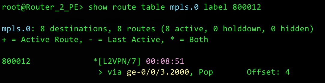
We were very confused when we spotted this “Offset: 4” in the MPLS label table. It seemed to have nothing at all to do with the offset we’ve been talking about in this blog. We spent a long, long time trying to work this one out. Why is the offset in the mpls.0 table? This table should be strictly a list of labels, and what to do with them. Something strange is happening here.
Luckily the mighty Yasmin Lara, my Juniper Ambassador colleague, worked it out: it’s referring to the fact that by default, a “Control Word” is negotiated. Despite the name, this isn’t actually a “word”. Instead, it’s an extra four bytes which are added in between the VPN label and the start of the packet. These four bytes serve a number of functions, and exactly what those functions are is a topic that we’ll save for another day. For now, all you need to know is the output above is telling the router that the packet really starts four bytes in from the usual starting place.
Good work to Bianca for spotting it; good work to Yasmin for working out the answer! If you see this yourself, don’t be confused: the word “offset” means something else in this context.
THAT’S IT!
How do you do L2VPNs in your organisation? Got any interesting stories about how they’re deployed? Let me know in the comments!
In the mean time, if you enjoyed this post, then a huge way to support my work is to share it on your favourite social media of choice. The more people that read my blog, the more I’m inspired to write even more posts.
If you’re on Mastodon, follow me to find out when I make new posts. (2024 edit: I’m also on BlueSky nowadays too. I was once on Twitter, but I’ve given up on it, on account of… well, I don’t need to finish that sentence, do I.)
An exciting competition I’m currently running is that my ten thousandth follower wins a -£200 voucher for a store of my choice. That’s right: minus two hundred pounds. Just to be clear, what I’m saying is that if you’re my ten thousandth follower, you have to buy me a £200 gift voucher. That’s your prize. Good luck!!
And if you fancy some more learning, take a look through my other posts. I’ve got plenty of cool new networking knowledge for you on this website, especially covering Juniper tech and service provider goodness.
It’s all free for you, although I’ll never say no to a donation. This website is 100% a non-profit endeavour, in fact it costs me money to run. I don’t mind that one bit, but it would be cool if I could break even on the web hosting, and the licenses I buy to bring you this sweet sweet content.


Thank you for your fun lesson!
Thanks for this, Chris. Did you get to do a piece on Control Word?
Have been doing bits for JNCIP and am testing both Kompella and Martini methods in the lab and the end result is effectively the same with minor differences in configuration – Kompella seemingly easier as no requirement for an underlying signaling protocol.
I’m trying to think of differences between the two that may cause you to choose one or the other when in the design process. Is there any reason you can think to choose one or the other? It seems like it would come down to vendor support and if they support both, personal preference. Perhaps Kompella because it’s technically less complex by taking LDP out of the equation…. even though it is just one line of config 😅. I suppose RFC 6624 defining the method is newer, which of course makes it better 😉
I just found your list of advantages above… that’ll teach me to skim through too fast. Less advertisements for greater scalability! Makes sense.
Thanks for the great content. I just read your post and want to make the payment for £750,000, but I cannot see the account details anywhere. Please help me, because there’s no way I will pay the £25 fine.
Thank you very much for reading!
Good point on the account details. Please look deep inside your heart to find the correct info. If you can’t find the details there, then don’t worry – they should come you in a dream tonight.