
INTERPROVIDER OPTION C, ON JUNIPER JUNOS ROUTERS – PART 2: THE THREE LABEL STACK, AND THE USE CASE VS OPTION B
In Part 1 of our journey into Interprovider Option C, we learned how to configure Juniper routers to extend an MPLS VPN between two autonomous systems. Along the way we made a few friends, broke a few hearts, and quite drastically increased the rate at which carbon is warming up the planet. Whoopsie-daisy!!
Anyway, in Part 1 we talked in detail about how Option C works, and how to configure it. We even pinged from one end to the other, to verify that it works. But there’s three things we didn’t do.
First, we didn’t talk about why we’d ever choose to use Option C, over Options A or B. Second, we only skimmed over this idea of the three-label stack. And third, we didn’t phone the people who mean the most to us, and tell them that we love them.
So, in this post we’re going to do all those things, and more. Along the way, we’ll be asking ourselves such questions as “What do labels taste like?”, “What is the meaning of life?”, and “If you put a plane on a massive conveyor belt, would it ever take off?”
…Sorry, I just re-read my notes, and actually we won’t be answering any of those questions. Apologies for the confusion there. This blog post is purely about MPLS, not the meaning of life. My mistake. Whoopsie-daisy!!
FOLLOWING THE LABELS, END TO END
Let’s remind ourselves of our topology again. As before, I recommend you give this picture a nice firm “click”, and open it in a new tab, because we’ll be referring back to it a lot.
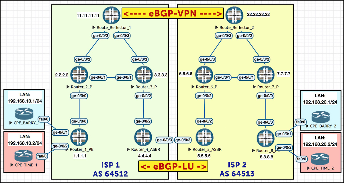
Okay, time to jump into the forwarding plane. If a host behind CPE_BARRY_1 (let’s say 192.168.10.5) sent a ping to a host behind CPE_BARRY_2 (let’s say 192.168.20.5), what would happen?
The packet leaves the source, and gets sent to its gateway, which is CPE_BARRY_1. This CPE router passes the packet to Router 1, at which point it enters the MPLS VPN. The packet gets label-switched to Router 4, crosses an AS boundary to Router 5, transits an MPLS network in ISP 2, reaches Router 8, at which point it gets passed to CPE_BARRY_2 – and then, finally, the packet arrives at its destination.
The full path is like this: CPE 1 > Router 1 > Router 2 > Router 3 > Router 4 > Router 5 > Router 6 > Router 7 > Router 8 > CPE 2.
What does Router 1 actually do when it receives the packet? First it notices that the packet came in on an interface that’s in a VRF, so it knows to look up the prefix in the VRF’s dedicated routing table. In doing so, Router 1 sees that 192.168.20.0/24 has a next-hop of 8.8.8.8 – and that it needs to add three labels before sending the packet on its merry way. In just a moment we’re going to look at a picture of all these labels. For now, follow us on the journey from end to end.
root@Router1> show route table BARRYS_ICE_CREAM.inet.0 192.168.20.0/24

BARRYS_ICE_CREAM.inet.0: 5 destinations, 5 routes (5 active, 0 holddown, 0 hidden)
+ = Active Route, - = Last Active, * = Both

192.168.20.0/24    *[BGP/170] 00:02:10, localpref 100, from 11.11.11.11
                      AS path: 64513 I
                    > to 10.10.12.2 via ge-0/0/0.0, Push 299936, Push 299984, Push 299808(top)
The inner label (299936) is the VPN label that Router 8 is advertising for this VRF. Nothing unusual there! This label only has meaning to Router 8. If any other router tries interpreting this label, it will be meaningless. This label is also known as the service label.
The outer label (299808) is the transport label that ISP 1’s LDP instance generated for getting to Router 4. There’s also nothing unusual here: this is the usual outer transport label we’d find when going between two routers within a single ISP.
The middle label (299984) is where things get interesting.
This middle label has a meaning only to Router 4. When the packet is sent by Router 3 to Router 4, Router 3 pops the outer transport label, as per the usual penultimate-hop-popping process. As a result, the label stack, which previously had three labels, now only has two.
This means that the label which was previously the “middle” label has been promoted to being the outer transport label! And, because it’s the outer label, it’s precisely this label that Router 4 processes. Router 4 knows that if it receives a packet with an outer label of 299984, it should swap it for label 300016 and pass it to Router 5:
root@Router4> show route table mpls.0 label 299984

mpls.0: 13 destinations, 13 routes (13 active, 0 holddown, 0 hidden)
+ = Active Route, - = Last Active, * = Both

299984             *[VPN/170] 00:18:42
                    > to 10.10.45.5 via ge-0/0/3.0, Swap 300016
And when Router 5 receives this packet, with an outer label of 300016, it knows to put the packet into the LSP towards Router 8:
root@Router5> show route table mpls.0 label 300016

mpls.0: 13 destinations, 13 routes (13 active, 0 holddown, 0 hidden)
+ = Active Route, - = Last Active, * = Both

300016             *[VPN/170] 03:07:23
                    > to 10.10.56.6 via ge-0/0/2.0, Swap 299872
From here, it’s business as usual. The packet goes down Router 5’s LSP to Router 8, and arrives at R8 with just one label (because of penultimate-hop popping). Router 8 looks up this label, sees it belongs to a VRF, pops the label, and passes the packet straight down the relevant AC (attachment circuit – basically a fancy word for the WAN link). This is the default behaviour in Junos. No need to inspect the destination IP – the label itself tells our PE router which WAN link to pass the packet down.
root@Router8> show route table mpls.0 label 299936

mpls.0: 6 destinations, 6 routes (6 active, 0 holddown, 0 hidden)
+ = Active Route, - = Last Active, * = Both

299936             *[VPN/170] 02:32:59
                    > to 172.16.20.2 via ge-0/0/1.0, Pop
As a result of all this magic, CPE1 can ping CPE 2!
CPE_BARRY_1>ping 192.168.20.1
Type escape sequence to abort.
Sending 5, 100-byte ICMP Echos to 192.168.20.1, timeout is 2 seconds:
!!!!!
THE LABELS, VISUALISED
Here’s what these labels look like visually. Notice the bottom VPN label stays the same, end-to-end. Also, notice how the label the starts as the “middle” label becomes the “outer” transport label as it enters ISP 2!
Finally, notice that between R5>R6 and R6>R7, the label is actually the same. This is a complete coincidence. This happened because my lab was extremely simple, so there’s not many prefixes that need labels. Make no mistake though: in effect, R6 is “swapping” a label for the same label!
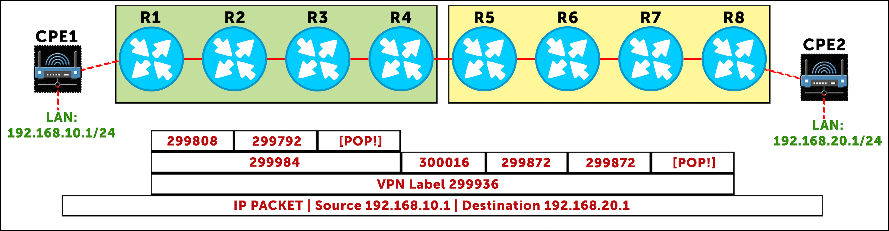
By visualising this, we again get to understand why Option C is so scalable: Router 1 has one single transport label to get to Router 8, which it uses for every single VPN prefix it knows. As far as Router 1 is concerned, the middle label it pushed to show that the packet is ultimately destined for Router 8, label 299984, is used even if there’s a hundred different MPLS VPNs being shared between the ISPs.
Let’s see this in practice. Router 1 has learned four VPN prefixes from Router 8. Notice how the top two labels (the middle one, and the one on the right) are the same for every single prefix. Only the left label changes, per-CPE. If that bit is confusing to you, hold fire, because in the next section we’re going to talk about exactly that concept.
root@Router1> show route table bgp.l3vpn.0 extensive | match Label
                Label operation: Push 299936, Push 300320, Push 299808(top)
                Label TTL action: prop-ttl, prop-ttl, prop-ttl(top)
                VPN Label: 299936
                Label operation: Push 299936, Push 300320, Push 299808(top)
                Label TTL action: prop-ttl, prop-ttl, prop-ttl(top)
                VPN Label: 299936
                Label operation: Push 300032, Push 300320, Push 299808(top)
                Label TTL action: prop-ttl, prop-ttl, prop-ttl(top)
                VPN Label: 300032
                Label operation: Push 300032, Push 300320, Push 299808(top)
                Label TTL action: prop-ttl, prop-ttl, prop-ttl(top)
                VPN Label: 300032
In Option A we needed a VRF/sub-interface/BGP peering for each VPN. In Option B we only needed the one BGP session, but our ASBRs (Routers 4 and 5) still needed a label for every prefix in every VPN. By contrast, our ASBR in Option C just advertises the one label, representing the loopback of the PE. Any information about the state of the VPN is kept at the edges – right where it should be!
WHEN WOULD WE USE OPTION C?
In this lab we’ve been pretending that each AS is a different ISP. However, due to the levels of trust involved in this setup, in practice Option C is mostly used within one single ISP that has multiple autonomous systems. Perhaps they have different AS numbers for different parts of the world, or perhaps they’ve just acquired or merged with another ISP. In either case, there really has to be an excellent trust relationship between the two “organisations” to extend MPLS in this way.
If ever you have a situation where you organisation controls both autonomous systems, choose either Option B or Option C. Option B is simpler, but puts more load on your AS border routers. Option C is more complicated to set up, but keeps the state where it belongs: on the PE routers and route reflectors.
Perhaps it still isn’t clear to you why it’s important to have control over both autonomous system. After all, it’s only labels. It’s not like we’re extending OSPF or IS-IS between the two. So, let’s take a look at the kind of action that the admins of one autonomous system could take which might severely impact the other AS.
THE DANGERS OF EXTENDING SOMEONE ELSE’S MPLS INTO YOUR OWN NETWORK
Picture, in your beautiful mind, three prefixes on two CPE routers. By default, a Juniper PE router generates only two VPN labels for these three prefixes: one label for each CPE router (to be precise, for each next-hop from the perspective of the PE). Or per-link, to be precise.
Let’s imagine that the two labels our PE router generates are 69 (nice), and 420.
- 10.10.10.0/24 on CPE 1 gets label 69 (nice).
- 10.10.20.0/24 on CPE 2 gets label 420.
- And 10.10.30.0/24 on CPE 2 also gets label 420 – because it’s on the same CPE.
Thanks to this behaviour, our Juniper router can receive a packet with label 420, and know immediately that the packet is destined to CPE 2, regardless of which of the two subnets the packet is ultimately destined for. This is a nice and efficient way of passing the traffic to the right place.
What if we turn on vrf-table-label? With this command, our Juniper router instead generates one label for all three of these prefixes – in other words, one label for the entire VRF.
Let’s imagine our router generates label 666 for all three prefixes. This means that when the PE router receives a packet with label 666, the PE has to pop the label, and do a second lookup on the IP header to see where the packet is ultimately destined to. It’s more work – but also allows you to implement firewall rules on the PE, because you’re forcing the PE to look at the IP header. There may also be QoS settings in the IP packet, which the PE might previously have not looked at.
So, imagine that ISP 2 is running vrf-table-label. Imagine as well that there were 100 MPLS VPNs shared between ISPs 1 and 2, and that in total ISP 2 hosted around 30,000 VPN prefixes. Thanks to vrf-table-label, let’s imagine we have something like 400 labels to represent all of these prefixes. PE1 can easily handle this many.
Now imagine that for some reason, ISP 2 turns off vrf-table-label. Suddenly, the PEs in ISP 1 are going to receive a massive increase in the number of labels that ISP 2 sends, because instead of one label per-VRF per-PE, it’s one label per-VRF per-CPE! That’s a BIG increase in state. Suddenly we could go from 400 labels to many thousands of labels. I say thousands: that’s a complete guess. I’ve not done the maths, and I’m not going to. You get my point though: you better cross your fingers that the routers in ISP 1 have enough memory for the sudden increase in labels.
If the other autonomous system really is owned by someone else, you have no control over whether they choose to do this. Actions by the other autonomous system could send a lot of new state to your PE router – and depending on what you’re getting that box to do, this could well be a problem!
This is why Option C is suited to situations where you’re the admin of both domains. Otherwise, the admins of ISP 1 might retaliate by doing something really nasty. You know: like swearing through ISP 2’s letterbox, or taking them off their Christmas Card list. Noooo, it’s too sad to even think about!!
THAT’S IT!
Except not really, because of course, this post is part 2 of three. And if you’ve read this far, I’m absolutely positive that you’re going to want the complete story.
Therefore, it is your mission, neigh your DUTY, to click here and read Part 3, where we first introduce RSVP into our network, and then we configure BGP-LU in a slightly different way. Will it take out MPLS VPNs down? Yep? Will we fix it? Click to find out…
In the mean time, you’ll do my the truest honour if you share this post on your favourite social media of choice.
If you’re on Mastodon, follow me to find out when I make new posts. (2024 edit: I’m also on BlueSky nowadays too. I was once on Twitter, but I’ve given up on it, on account of… well, I don’t need to finish that sentence, do I.)
And if you fancy some more learning, take a look through my other posts. I’ve got plenty of cool new networking knowledge for you on this website, especially covering Juniper tech and service provider goodness.
It’s all free for you, although I’ll never say no to a donation. This website is 100% a non-profit endeavour, in fact it costs me money to run. I don’t mind that one bit, but it would be cool if I could break even on the web hosting, and the licenses I buy to bring you this sweet sweet content.