

JUNOS: CHASSIS CLUSTERS – A BEGINNERS GUIDE TO JUNIPER SRX HIGH AVAILABILITY
Okay pals, I’ll level with you – this is one of the first posts I ever wrote on this website. I was very new to Junos at the time. I’m not a firewall person, and this post was not written from authority.
BUT.
The comments on it have been extremely nice, and people seem to have found genuine value from it Lots of folks have found it helpful. I’m delighted that I got lucky.
As such, I’m leaving this post up in case it continues to be helpful – but I’m afraid I can’t help with any questions that people might have.
Want to learn how to configure Chassis Cluster, which lets you configure high-availability failover on Juniper firewalls? Good luck with the official documentation – this instruction manual weighs in at precisely 638 pages long. 638 pages! That’s the length of two good books! Or one badly edited one.
It’s not fair that reading long instructions manuals doesn’t count as a plus-one on the number of books you’ve read. For example, when I went on a date recently and was asked what the most recent book I read was, she turned her nose up when I told her that “Chassis Cluster Feature Guide For SRX Series Devices” by “Juniper Networks” was a real page turner.
Anyway. This article is my attempt at boiling those 638 pages down into something a bit more manageable. You can thank me by emailing me £700,000.
This post is NOT a complete guide to HA redundancy. Chassis Cluster is a big concept, and there’s lots you can do with it. Instead, this post is meant for people who needs to quickly learn the high points, and how to read and understand what’s going on in the average real-world configuration.
Does that sound like you? If not, please stop reading immediately. It is illegal for you to read any more, and the FBI will be informed. (Jokes: everyone is welcome here, and I hope you find this post helpful!)
In a moment I’ll show you some of the high points you’ll see in the average configuration. First though, let’s talk about the concepts that you need to know.
HOW DO CHASSIS CLUSTERS WORK?
Chassis Cluster is Juniper’s name for it’s High Availability (HA) technology.
The philosophy is quite simple: you get two SRX firewalls, and link them up using something that movie stars like to call “cables”. One device becomes the “Primary”, and one the “Secondary”.
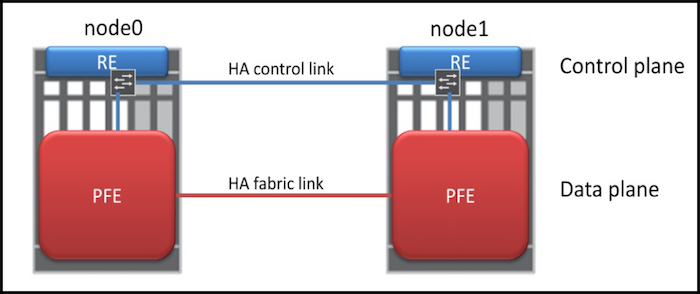
You actually connect the devices using two cables, and each cable has a special purpose.
One cable is known as the Fabric Link, and it’s the cable that the devices use to share session information between the Packet Forwarding Engine, or PFE. In certain setups, user traffic also travels across this link.
The fact that the session table is stored on both devices means that if the Primary SRX goes down, the Secondary can take over without dropping anyone’s downloads. This means that your users won’t experience any downtime while illegally torrenting the latest mp3s by popular olden-days bands like Hootie and the Blowfish, or Johnny Hates Jazz.
The other cable is called the Control Link, and it’s used for all control plane traffic. The control plane is the part of the device that deals with anything that isn’t forwarding traffic: routing protocols, maintaining the routing table, dealing with Telnet/SSH sessions, system configuration, SNMP, and so on.
NODES, CLUSTER IDs, AND REDUNDANCY GROUPS
Cool fact: the devices in a HA pair are called Nodes. The primary node is called node0 (that’s node zero), and the secondary is node1 (that’s node one). Once you’ve set them into HA mode, they share one configuration. Logging onto either device configures both. “Wow!”.
The two devices also share a thing called the cluster-id, which is a number that identifies which cluster the firewalls are in.
Devices can only be in one cluster at a time. So you may ask: hang on – why do you have to configure a cluster-id, when a device can only be in one cluster at a time anyway? Here’s why: because the interface’s shared virtual MAC address is generated using the cluster ID number you choose. This lets you have multiple different clusters, all on one LAN segment.
The cluster-id is a number between 1 and 255. And hey, here’s something: You can choose whatever number you like! It’s Juniper’s way of saying “Have a little bit of fun today”.
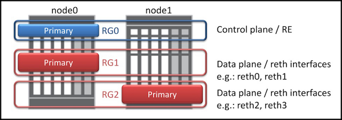
Within each cluster you can also have multiple Redundancy Groups. This lets you configure your network so that node0 is the Primary for a certain part of the network, and node1 is the Primary for a different part, like in the diagram on the right. (Notice that the pic mentions something called a reth interface. I’ll tell you what that is in a moment.)
Bonus trivia: redundancy-group 0 is reserved for the control plane, and the Primary device controls the control plane for both devices. This makes both devices almost act as if they’re one device. For example, you can still log on to each device individually, but any configuration changes to one device affects both, because they share one configuration.
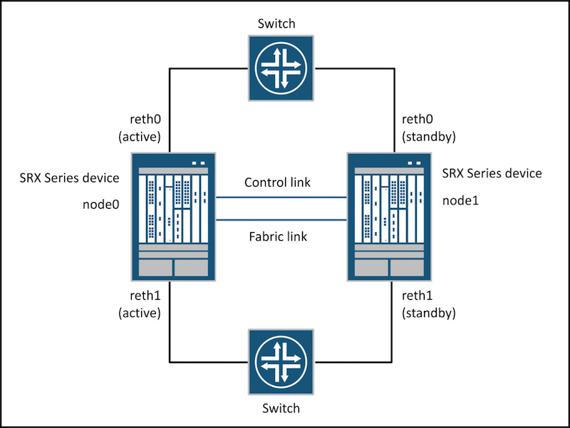
VIRTUAL “REDUNDANT ETHERNET” INTERFACES
The aim of high availability is that if a primary device goes down, a secondary device should immediately take over. This means that both devices need to have an interface in each network segment, whether it be LAN facing or WAN facing.
If you’re familiar with things like HSRP and VRRP, you’ll know that usually it works something like this: you give each interface its own IP address for management purposes, then you also configure each interface with a second, shared IP address. Devices on the network segment use that shared IP as their default gateway. Also, you tend to only configure it on the LAN segments, not on the WAN facing side.
Junos works a little differently.
In Junos, you actually create a new virtual interface, and attach the physical interfaces to the virtual interface. These new virtual interfaces are called Redundant Ethernet interfaces, or reth interfaces (pronounced “reeth“, to rhyme with “teeth”).
As I said earlier, the two firewalls share a common MAC address on the ethernet segment they’re on. If the Primary device loses its primary status, the Secondary devices sends out a gratuitous arp to the network, telling everyone to come to it instead. This makes the transition from one primary firewall to the other completely invisible to all devices on the network. Gosh, it’s so beautiful, it almost brings a tear to my eye!
Here’s how you make a reth interface:
• First you define how many of these virtual Redundant Ethernet interfaces you want, using the reth-count command.
• Then you put these reth interfaces into a redundancy-group.
• Next, you configure the reth interfaces with whatever properties you like – units, families, IP addresses, VLANs etc.
• Finally, you assign the physical interface on each firewall to your new virtual interface.
We’re almost ready to actually see some configuration! There’s just one more thing you need to know before we begin.
PHYSICAL INTERFACES, AND HOW THE NAMES CHANGES
Something interesting happens to the names of the physical interfaces when you put a device into a HA pair.
Imagine: you’ve got two identical SRX’s. You couldn’t be happier. Ever since you were a kid you wanted two identical SRX’s, and now your dreams are over.
When you set up two devices in a Chassis Cluster, the two devices share one configuration file. Think about the consequences of that: if the two firewalls are sharing one configuration and one control plane, and you were to type the command show interface ge-0/0/0, how does the SRX know if you’re referring to ge-0/0/0 on the primary, or ge-0/0/0 on the secondary?
To fix this problem, Junos renames the interfaces on the Secondary interface. For example, the interface that was previously called ge-0/0/0 on the Secondary firewall might now be called ge-5/0/0.
I say “might” because, if I’m not mistaken, it changes depending on exactly what model of firewall you’re using. Sometimes it’ll be ge-5/0/0, sometimes it’ll be ge-3/0/0, sometimes ge-9/0/0, and more. It’s annoying, but the renaming happens automatically, so just check your config to see what the wisdom of Junos has decided to use. I’m sure there’s a reason for it. I’m very much an amateur at this stuff, so I’m not going to judge.
SETTING THE FABRIC PORT
Here’s the two lines of configuration to look out for when you see a chassis cluster config for the first time. These two lines make the fabric link work. We define two virtual fabric interfaces, and then assign a physical interface on each firewall to them.
set interfaces fab0 fabric-options member-interfaces ge-0/0/2
set interfaces fab1 fabric-options member-interfaces ge-5/0/2
If you want to know which interface to use for the fabric port, read this page, which also helpfully tells you what the FPC port will change to.
LET’S CONFIGURE SOME VIRTUAL INTERFACES
Check out this slice of config. Let’s make two virtual interfaces, reth0 and reth1, and put them into a redundancy-group:
set chassis cluster reth-count 2
set interfaces reth0 redundant-ether-options redundancy-group 1
set interfaces reth1 redundant-ether-options redundancy-group 1
reth0 and reth1 are now interfaces like any other, and you can configure them however you like. For example, you can give them IP addresses:
set interfaces reth0 unit 0 family inet address 90.90.90.1/24
set interfaces reth1 unit 0 family inet address 10.1.1.1/24
Basically you can do anything you like to a reth interface. Apart from marry it. Reth interfaces are not to be married. You can love them as much as you like, but they’ll never love you back.
Adding physical interfaces into a virtual reth interface is super easy. Let’s put the ge-0/0/14 interfaces into reth0, and the ge-0/0/15 interfaces into reth1. Notice that on the Secondary device, the name of the interface has changed from ge-0 to ge-5:
set interfaces ge-0/0/14 gigether-options redundant-parent reth0
set interfaces ge-0/0/15 gigether-options redundant-parent reth1
set interfaces ge-5/0/14 gigether-options redundant-parent reth0
set interfaces ge-5/0/15 gigether-options redundant-parent reth1
You can even do automatic aggregated Ethernet (what Cisco calls Etherchannel) by just assigning multiple physical interfaces into a reth interface. Which is pretty cool, if you ask me! And even if you don’t ask me.
All you need to do now is put the reth interfaces into the relevant zones:
set security zones security-zone untrust interface reth0.0
set security zones security-zone trust interface reth1.0
If you want more reths in the future, just change the reth-count. (Wow, imagine saying that sentence to your Nan. She’d think you were mad.)
DEFINING WHICH FIREWALL BECOMES THE PRIMARY
If you’ve done any kind of HA before, you’ll know this concept: you give the nodes a priority value, and the one with the biggest number becomes the primary. You actually assign the priority to the redundancy-group, which is how you can do the load-balancing we mentioned above: you could have node0 become Primary for redundancy-group 1, and node1 become the Primary for redundancy-group 2, if you wanted to.
We also add in some sweet sweet preempt, so that if the node1 does have to take over as Primary, node0 will take it back when it comes back online.
set chassis cluster redundancy-group 1 node 0 priority 150
set chassis cluster redundancy-group 1 node 1 priority 100
set chassis cluster redundancy-group 1 preempt
HOW TO MAKE THE DEVICES FAILOVER
If one firewall dies, the other will take over. By default, the secondary firewall will take over if it doesn’t receive a heartbeat from the primary after 3 seconds.
Of course, we also want the Secondary to become Primary if even one interface goes down. Here’s how you do it.
Each redundancy-group is configured with a “weight value” of 255 by default. Junos can monitor the state of certain interfaces, and if those interfaces go down, it can lower the group’s weight value to whatever you like. When the weight value reaches 0, the failover kicks in.
For example, if you want the failover to kick in if even one interface goes down, do it like this:
set chassis cluster redundancy-group 1 interface-monitor ge-0/0/14 weight 255
In other words “If ge-0/0/14 goes down, reduce the weight by 255”. 255 minus 255 equals 0. That’s maths!
Alternatively, maybe you want the Secondary to kick in only if two interfaces go down. In that case, it’s like this:
set chassis cluster redundancy-group 1 interface-monitor ge-0/0/13 weight 150
set chassis cluster redundancy-group 1 interface-monitor ge-0/0/14 weight 150
When the first interface goes down, the weight value of redundancy group one will go down to 105 (255 minus 150). It’s not until the second interface also goes down that the failover happens.
You can even monitor the reth interface. A reth interface goes down when all the physical interfaces attached to the reth go down.
And of course, there’s an ip-monitoring command that lets you failover if the cluster loses reachability to a certain IP address.
LET’S END WITH SOME HANDY SHOW COMMANDS
Do a show chassis cluster status to check that your firewalls are up and working as expected:
juniper1> show chassis cluster status

Cluster ID: 1
 Node                      Priority        Status       Preempt   Manual failover

Redundancy group: 0 , Failover count: 0
     node0                200             primary           no        no
     node1                100             secondary         no        no

Redundancy group: 1 , Failover count: 0
     node0                200             primary          yes        no
     node1                100             secondary        yes        no
Let’s have a look at the status of the interfaces. This command shows us which interfaces are up, and by how much the weight will drop if they go down:
firewall1> show chassis cluster interfaces | find Monitoring
 Interface Monitoring:
    Interface        Weight    Status        Redundancy-group
       ge-5/0/15     150           Up        1
       ge-5/0/14     150           Up        1
       ge-0/0/15     150           Up        1
       ge-0/0/14     150         Down        1
Woah, ge-0/0/014 is down! Let’s do a show chassis cluster information, to see the result of this interface being down. Look at the Threshold for Redundancy group 1 on node0 – it’s gone down to 105. Not enough to make things fall over to node1, but enough to reduce group 1’s threshold on node0 to 105:
juniper1> show chassis cluster information

node0:
 --------------------------------------------------------------------------
 Redundancy mode:
   Configured mode: active-active
   Operational mode: active-active

Redundancy group: 0, Threshold: 255, Monitoring failures: none
  Events:

Redundancy group: 1, Threshold: 105, Monitoring failures: interface-monitoring
  Events:

node1:
 --------------------------------------------------------------------------
 Redundancy mode:
   Configured mode: active-active
   Operational mode: active-active

Redundancy group: 0, Threshold: 255, Monitoring failures: none
  Events:

Redundancy group: 1, Threshold: 255, Monitoring failures: none
  Events:
THAT’S IT FOR TODAY!
There’s so much more to learn about Chassis Cluster, but you’ve now got enough knowledge to be able to work out what’s going on when faced with two SRX’s in HA mode.
If you’d like to know even more, with an aim to configuring it, I recommend this 35 page PDF, which is a bit easier on the brain than the 638 page guide! It gives a full config, and a few different topologies. It’s also where I got the diagrams that I used in this post.
If you’re on Mastodon, follow me to find out when I make new posts. (2024 edit: I’m also on BlueSky nowadays too. I was once on Twitter, but I’ve given up on it, on account of… well, I don’t need to finish that sentence, do I.)
And if you find my blog useful or entertaining, I’d love you to share it with your friends and co-workers, whether via a Twitter/Facebook/LinkedIn post, or just emailing it to them directly. Spread the world, and I’ll be inspired to write even more posts.
And if you fancy some more learning, take a look through my other posts. I’ve got plenty of cool new networking knowledge for you on this website, especially covering Juniper tech and service provider goodness.
It’s all free for you, although I’ll never say no to a donation. This website is 100% a non-profit endeavour, in fact it costs me money to run. I don’t mind that one bit, but it would be cool if I could break even on the web hosting, and the licenses I buy to bring you this sweet sweet content.


Hey Chris,
Great post! Two quick questions however:
1. How do you configure the fabric ports on an SRX? No fabric == no worky 🙂
2. As an extension to #1 – are you planning on doing another blog post for L2 switching in a SRX cluster?
Hi there Clay! Thanks for the kind words. Ooh good idea on the L2 switching. It isn’t something I have hands-on experience with, but I get the feeling that that might change at my employer in the coming months. When it does then I’ll absolutely write it up. And if I can get around to labbing it up before then, then I’ll write it up too. 🙂
Good call on the fabric ports, I’ll add that in. Thank you for the feedback!
Love this, we will be sharing on our channels!
Aww thank you very much Julie! That’s very kind of you 🙂
Hey Chris,
Great post – love your writing!
Regarding the interface numbering for different SRX models: Because Junos allows you to configure non-reth interfaces (eg: normal L3 interfaces) on each node that operate normally regardless of the state of any redundancy-groups, there needs to be a way of uniquely identifying a port on node1 vs the same port on node0. This is why each port gets a unique identifier.
The numbering mechanism is just a continuation of the FPC numbering that each box supports – eg: an SRX354 has FPCs 0-4 (built-in ports plus 4 modular slots), so the built-in ports on node1 will start at ge-5/0/0.
This way, you can still have ge-0/0/6 and ge-5/0/6 as stand-alone links to different ISPs or similar.
Cheers,
Ben
Cheers Ben! Thanks for the kind words, and for that clarification. I’m grateful to you for taking the time to write it!
Chris,
I just read your quick article on SRX clustering which is very good. I had a quick question related to SRX clustering, that I have been wondering about for several months, but have been unable to get a direct answer for.
I have been using SRX clusters for a while, and If I had to do it again I would split them and use high availability protocols like BFD for my redundancy. I am curious what others in the industry are doing? Is everyone gung-ho, all in on clustering, or are people implementing redundant SRXs without clustering to ensure high availability?
In theory SRX clustering is good. My redundant node has the firewall existing firewall state for the RG so if a failure occurs the firewall state will continue on the redundant node. But in all actuality; I have experienced way worse outages due to cluster split brain conditions. First, cpu spikes causing lost heartbeats, then simple card/port/cable failures causing lost heartbeats. Each firewall Node then thinks its active for the Redundancy Group, and each Node is GARPing the MAC address for the Reth. All of these of these incidents caused way worse outages than a few seconds it would take to route around the bad card/port/cable, or deal with a momentary CPU spike. Then to get the firewalls out of split brain they need to be rebooted. Its hardly high availability.
Brendan
Gosh, that’s an interesting one. I don’t suppose you know what’s causing the CPU spikes? It’s not something I’ve seen before, but I’ll be interested to see if anyone else has ever experienced this. Apologies that I can’t answer this one myself Brendan, but if you ever raise it with Juniper direct I’d love to hear what they come back with.
By the way, if you’re not sure what’s causing the spikes, I just found this post that might help get to the bottom of it: https://duncanbowring.wordpress.com/2012/04/23/strange-juniper-srx-performance-spikes-9-2/ – you’ve probably seen it before, but I’ll share it just in case.
That’s a great material, Chris. Took like 15 min to understand which should take 15 days with Juniper Documentation 😉
Haha, thank you mate! Genuinely happy to hear that my silly website helped you to understand it.
Excellent and funny written to make these concepts be easier to digest.
Hi! Can You recommend a documentation or other source of information on OSPF behavior on chassis cluster? It was kind of a surprise for my team that every failover causes OSPF neighborships drops, traffic flow interruption for over 10 seconds. We were new to Juniper SRX implementing in a hurry and now have a production WAN edge SRX cluster working like this. Any chance to make it work better or it’s by design?
Gosh, I’m afraid I don’t know the answer to that question. That post I wrote pretty much contained my sum knowledge about chassis clusters! I bet that if you were to ask that question on the Juniper forums there’d be a hundred people who could help with it though.
Hi. I do not have direct experience with graceful OSPF setup on SRX cluster, but that is probably something you need to look into. I believe the RG0 handles all the routing. If the failover is longer that the OSPF dead timer I think it is just a lost cause, but if the failover is within the time limit you might be able to do somethin with graceful restart or other features to avoid converging.
Let us know how you progress with this.
Bonus Tip: with the cluster-id, if you have more than 1 cluster on a Ethernet broadcast domain with the same cluster-id, you will run into MAC address collisions!
found this one by accident at 2am with an angry customer phone call, after shifting some networking around. suddenly traffic wasn’t going out that VPN like it was supposed to.
Wow what a headache! A good protip, thank you!
I have spent two days reading “JNCIS-SEC Study Guide”, until I found your publication. I want to thank you for the valuable information you provide to the community.
Thank you Chris!
Really glad I could help you out. Cheers Alex!
Excellent stuff!
For F* Shake !!
I’ve been looking this kind of article for too long !!
coming from Fortinet, i find Junos OS really hard to digest !
And ur article help me a lot compared to official KB too scientist
Thanks ! (Like the humor !)
Thank you very much! 🙂 (Sorry for the slow reply!)
Great Article!!!
Stumbled upon this article while searching for chassis-cluster. But bookmarking this site for the jokes.
Hopefully down the line, when I become a billionaire, I will definitely come back to this article to donate the £700,000.
Until then, love you 3000 (unless you are a Tottenham Hotspur fan)
Haha, well I’m not a fan of football in general, however I can say that the bill has now risen to £700,001, due to inflation. I’ve tried to be reasonable with my prices, in keeping with the cost of living crisis.