

INTERPROVIDER OPTION C, ON JUNIPER JUNOS ROUTERS – PART 1: CONFIGURATION WITH LDP (INCLUDES FULL TOPOLOGY CONFIG!) (JNCIP-SP, JNCIE-SP)
When I was young, my granddad used to say to me “Son, you’ll never extend an MPLS VPN between two autonomous systems. It can’t be done.” Well, guess what Granddad: you were wrong, plus you were an idiot. Maybe they couldn’t do it in the 1940s, but today we can do it easily. Shut up, Granddad. Shut up.
In previous posts we’ve seen two ways to do extend MPLS VPNs between two ISPs. In our post on Interprovider Option A we saw how we can treat the other ISP as if they were just another customer of ours. Then, in our Option B post we saw that we can actually exchange VPN labels with the other ISP, over a dedicated link.
Today we’re going to look at Interprovider Option C, so-called because it’s the third suggestion on the actual RFC for MPLS VPNs.
Option C isn’t too hard to understand, in principle. However, there’s a fair number of pieces needed to actually get it working. In addition, depending on exactly what protocols you’re using, and depending on where you’re storing your prefixes, there’s a looooooot of tweaks you need to know about.
That’s why this blog post is the first of three. Why three posts? There’s plenty of other guides out there that give you a quick run-down on the high points about Option C. These posts are going to do the opposite. By the end of this three-parter, we’ll know Option C inside-out:
- In this first post we’ll see a “basic” Option C config, with both ISPs running LDP.
- In our second post, we’ll take a look at the labels involved, because there’s something very unique about the label stack in Option C. We’ll also talk about the use case. Why would we ever use Option C, over Option A or B? In Part 2, we’ll find out.
- Finally, in our third post, we’ll reconfigure one of our ISPs to run RSVP, and we’ll also make a few other changes too. We’ll see how these changes break things – and then, we’ll see how to fix them.
Fun fact: Option C is the most complicated solution to set up, but once it’s actually up and running it’s also the most scalable. Why? In just a moment, you’ll find out. But first:
REQUIRED KNOWLEDGE FOR THIS POST
If you’ve just arrived here after a Google search for something like “Juniper inter-AS option C”, you might like to know that I’ve also done posts before on Interprovider Option A and Interprovider Option B. In fact, this post uses the same topology and configuration. With that in mind, you might want to read those posts first.
It’s not essential to read them – but I would still highly recommend it, because in those posts we set up the two-ISP lab that we’re going to use today. We also introduced a few concepts that we’ll be referring to again in this post, like the difference between service and transport labels, and the concept of BGP AFI/SAFI.
In addition, you’ll definitely want to be familiar with the concept of BGP-Labeled Unicast. If you’re not, don’t worry: I wrote a post all about it, especially so that you can understand it! Go give it a read if you don’t know about it already.
If you’re already comfortable with LDP, RSVP, OSPF, IS-IS, BGP, BGP-LU, and address families, and you just want to learn some sweet sweet Option C, then let’s gamble: jump right in! Just know that if you find yourself feeling confused at any point, you can go back and read the previous posts to get up to speed.
And if at any stage you find yourself feeling aroused, then don’t worry: it’s a natural reaction to reading my posts.
HOW OPTION C WORKS: THE SHORT VERSION
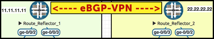
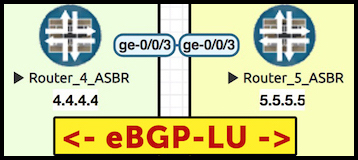
Take a look at our topology below. Notice that there’s two route reflectors, one in each ISP. There’s also one dedicated link connecting the two ISPs, between routers 4 and 5. Take half a minute to properly understand this topology. Notice that each router has a loopback which is just the number of the router, so Router 8 is loopback 8.8.8.8. The one exception is the route reflectors – notice that Reflector 2 is 22.22.22.22.
My advice to you: open this pic in a new tab, because we’ll be referring back to it throughout the course of this post. Click the pic to make it big:
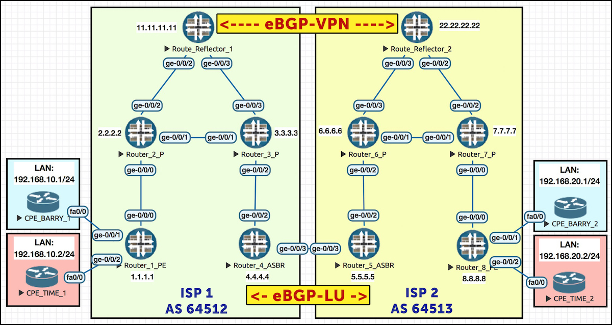
Here’s how Option C works: the route reflectors in each ISP are actually going to talk directly to each other to exchange VPN prefixes, each route reflector acting as a client of the other. This is rare: usually route reflectors only reflect routes within their own autonomous system. In this scenario though, we’re reflecting from one ISP to the other. Dare to dream, friends! Dare to dream.
Immediately here, we see one of the reasons why Option C is more scalable. In Option A, our ASBRs (Autonomous System Border Routers – Routers 4 and 5 in our topology) needed to hold a ton of state in their memory, like all the prefixes for all the VRFs, the VRFs themselves, plus BGP sessions. In Option B our ASBRs still needed to hold a lot of state, remembering a label per-prefix per-VRF. However, in Option C all of this state is moved to the PEs and the route reflectors, where the state belongs. All our ASBRs need to be aware of is the fact that they’re part of a transit label-switched path
The reason this is possible is thanks to the unique way our route-reflectors advertise the next-hop for these VPN prefixes. In the pic above our PEs are Router 1 and Router 8. When Router 1 advertises a VPN prefix to its route reflector, the prefix has a next-hop of 1.1.1.1. Reflector 1 then advertises this to Reflector 2, at which point Reflector 2 reflects it to Router 8 – still with a next-hop of 1.1.1.1!
In other words, Router 8 sees Router 1 – a router in a totally different autonomous system – as the next-hop! The next-hop doesn’t change at any step of the way, even though we’re crossing an autonomous system boundary. This is in deep contrast to options A and B, where the border routers told the other ISP that the border router itself was the next-hop.
Here we see another example of the scalability of Option C. Once again, we’re relieving our border routers of keeping track of state, and keeping that responsibility where it belongs, because the ASBRs don’t need know they’re the next-hop for every single individual VPN prefix. As long as they know the LSP (label-switched path) to put the traffic on, that’s all that’s needed.
Now, the sharp thinkers among you might be thinking: how does Router 8 resolve the IP address of Router 1? Even if Router 1’s loopback (1.1.1.1) happened to be in Router 8’s routing table, that’s not enough: for an MPLS VPN, running private IPs over a provider network, we need a label-switched path from R8 all the way to R1. How on earth does this work? How?!?
To understand that, we need to know about SAFI 4, otherwise known as BGP Labeled Unicast. And it’s important that we understand it in detail. That’s why I’ve written an entire post all about it! Click here to read my blog post on BGP Labeled-Unicast, on Juniper routers. Once you understand what it is, how it works, the default behaviour, and how to manipulate it, come back here. Don’t worry, I’ll wait. Take your time: I’ve got lots of Super Mario to catch up on.
Done? Perfect. So: we have route reflectors talking directly to each other, exchanging VPN prefixes, with the next-hop unchanged. Meanwhile, our PE routers in each ISP have a full label-switched path to the PE in the other ISP, thanks to our border routers talking BGP-LU with each other. Router 8 knows a label for Router 1. If you still can’t quite picture how that works, don’t worry: later on we’ll be talking about it in great detail.
RESETTING OUR LAB
In previous posts we set up our IGP, our iBGP, and our VRFs. This post picks up where we left off, so we won’t go over all that again.
You’ll remember that we’re running IS-IS in ISP 1, and OSPF in ISP 2. I’m going to change my lab a little bit, and just run LDP everywhere in both ISPs. This will help us focus on what makes Option C unique. (As I mentioned earlier, in Part 3 we’ll be bringing RSVP back, to see how it changes things.)
TURNING ON OPTION C: OUR PLAN OF ACTION
One of the things we’re going to configure is an eBGP multi-hop peering directly between Reflector 1 in ISP 1, and Reflector 2 in ISP 2. This peering will only talk the VPN unicast family.
We’re also going to run BGP-Labeled Unicast between our ASBRs, Routers 4 and 5, so that each ISP receives labeled routes to the PEs and route reflectors of the other ISP. We’ll add a policy onto it, to make sure we’re only advertising what we need to advertise.
How about the VPN route-targets for each VRF? It’s common for an ISP to use their autonomous system in the target, so if we’ve got VPN prefixes coming from a different AS, we need to give this some thought.
In our Option B post we learned how to re-write communities as routes pass from one AS to another, using a policy. It’s not hard, but it involves a lot of lines of config. Because we’ve already seen what that looks like, in this post we’ll just do a simple solution, and import both ISP 1 and ISP 2’s target communities into each VRF.
Soon enough we’ll be ready to start configuring. But before we jump into it, let’s take a look at what should happen when it’s all working.
THE EXPECTED RESULT: OPTION C’s THREE-LABEL STACK
You’ll remember that the aim of all this is to give Router 1 a labeled path to 8.8.8.8, and Router 8 a labeled path to 1.1.1.1.
Here’s what’s going to happen: ASBR Router 5 will generate a label for 8.8.8.8 (the loopback of Router 8), and pass this label to Router 4. R4 will then generate a new label to get to Router 8 (when a router advertises itself as the next-hop, it always generates a new label), and R4 will advertise this labeled route throughout ISP 1. As such, Router 1 will receive it.
So, after all that, if PE Router 1 wants to send traffic to a VPN prefix with a next-hop of 8.8.8.8, what will Router 1 actually do? Here’s where things get really interesting: Router 1 will actually push THREE labels onto the packet:
• First, R1 pushes an inner VPN label, useful only to R8, to identify the VPN itself.
• Next, R1 pushes a middle label that won’t be processed until we get to R4. This is the label that tells R4 how to get to R8, via R5. We’ll talk about this label more in a moment.
• Finally, a top outer transport label, which identifies the label-switched path from R1 to R4.
Crikey! Cor blimey gov’nor! Apples and pears! That’s a lot of labels. Again, don’t worry if you can’t visualise that, because once we’ve configured it all and got it working we’ll move over to Part 2 in this series, where we’ll look at a diagram that shows exactly how the label stack works, end-to-end.
ON WHICH ROUTER SHOULD WE REDISTRIBUTE OUR LOOPBACKS INTO BGP?
Now, which step should we configure first? The BGP-LU peering between the two border routers, or the BGP inet-vpn unicast peering between the route reflectors?
Well, we can’t set up the reflector peering just yet, because our route reflectors don’t have routes to each other. They’ll only know about each other’s loopback when the BGP-LU peering comes up.
As such, t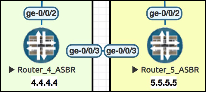 he very first thing we’ll do is turn on BGP between our ASBRs – Routers 4 and 5. Remember, in this example we’re specifically going to turn on only BGP-Labeled Unicast, because this link is dedicated to VPN transit traffic. We have no need for regular public BGP IPv4 unicast (AFI 1/SAFI 1) here.
To make this nice and clean, we’re going to configure a policy on R4 which takes the relevant loopbacks in ISP 1, and sends them to R5 via eBGP. Labeled, naturally! Without this policy, there’s a danger that Router 4 would advertise everything via BGP to Router 5. And of course, we’ll do the same on R5, making a policy to advertise ISP 2’s important loopbacks as labeled prefixes.
Now, it may not be immediately clear why we’re choosing to redistribute these loopbacks into BGP at our ASBRs in particular. For example, if Router 1 is talking BGP to the rest of ISP 1, why don’t we redistribute 1.1.1.1 into BGP on Router 1 itself? Why not redistribute it at the source of the prefix?
The answer comes in the behaviour of route reflectors. Let’s imagine that we turned BGP labeled-unicast on everywhere in ISP 1, and that we added a policy on Router 1 itself to redistribute its loopback into iBGP. Here’s the result: R1 sends its loopback address, 1.1.1.1, via iBGP to its route reflector. As such, our plucky route reflector will indeed receive the prefix, with a label:
root@Reflector1> show route receive-protocol bgp 1.1.1.1 1.1.1.1/32 extensive

inet.0: 13 destinations, 18 routes (13 active, 0 holddown, 0 hidden)
  1.1.1.1/32 (3 entries, 2 announced)
      Accepted
      Route Label: 3
      Nexthop: 1.1.1.1
      Localpref: 100
      AS path: I
(The command above can look confusing with the two 1.1.1.1 entries. The red one is the address of Reflector 1’s BGP neighbour. The blue one is the actual route we’re looking up. By coincidence, in this example the two addresses are the same!)
But look o’er yonder – Reflector 1 isn’t actually reflecting this route on to Router 4:
root@Reflector1> show route advertising-protocol bgp 4.4.4.4 1.1.1.1/32 extensive

root@Reflector1>
Why? For our answer, let’s take a look at 1.1.1.1/32 in Reflector 1’s inet.0 table.
root@Reflector1> show route table inet.0 1.1.1.1/32

inet.0: 13 destinations, 14 routes (13 active, 0 holddown, 0 hidden)
+ = Active Route, - = Last Active, * = Both

1.1.1.1/32          *[IS-IS/18] 00:00:04, metric 20
                    > to 10.10.112.2 via ge-0/0/2.0
                    [BGP/170] 00:05:27, localpref 100, from 1.1.1.1
                      AS path: I
                    > to 10.10.112.2 via ge-0/0/2.0, Push 299776
It’s in there twice – once as an IS-IS route, and once as a BGP route. Reflector 1 has rightly chosen the IS-IS route as the route that it thinks is best…. and because the BGP route isn’t the most preferred route, it isn’t reflected to Router 4.
Remember, reflectors don’t just take every prefix they get, and reflect the whole lot. They actually go through the BGP path selection process themselves, and only select the winners. And as an extensive output shows, this route was not the winner:
root@Reflector1> show route table inet.0 1.1.1.1/32 protocol bgp extensive | match Inactive
                     Inactive reason: Route Preference
There’s ways around it, of course – but in our lab, we’re going to put the loopback into BGP at the edge of our network. That way, we can be very specific about which labeled unicast prefixes we choose to pass to our friends in the other ISP.
CONFIGURING OPTION C – ADVERTISING LABELED-UNICAST PREFIXES TO THE OTHER ISP
Let’s start configuring! Remember to have the topology handy in a different tab, so you can refer to it as we talk about all the different routers.
First we’re going to turn on BGP-LU between our two ISPs, at ASBRs Router 4 and Router 5. I’m also going to apply a policy to export only the loopbacks of our PE routers, and the loopbacks of our route reflectors. That’s quite a mouthful, so let’s look at some config to see what’s going on. Here’s the BGP config on Router 4:
set protocols bgp group TO_AS64513 type external
set protocols bgp group TO_AS64513 family inet labeled-unicast rib inet.3
set protocols bgp group TO_AS64513 export R1_LOOPBACK_IN_LABELED_UNICAST
set protocols bgp group TO_AS64513 peer-as 64513
set protocols bgp group TO_AS64513 neighbor 10.10.45.5
You’ll remember from my post on BGP-LU that we often choose to put the prefixes into inet.3. As for the policy, here it is in hierarchy format so it’s a little easier to read:
root@Router4> show configuration policy-options policy-statement R1_LOOPBACK_IN_LABELED_UNICAST

term ACCEPT_R1_LOOPBACK {
    from {
        route-filter 1.1.1.1/32 exact;
        route-filter 11.11.11.11/32 exact
    }
    then accept;
}
term ELSE_REJECT {
    then reject;
}
We’ve also added the equivalent config on Router 5.
Did it work? Let’s see what ISP 1’s ASBR (R4) is learning from ISP 2’s ASBR (R5):
root@Router4> show route receive-protocol bgp 10.10.45.5 extensive

inet.0: 15 destinations, 15 routes (15 active, 0 holddown, 0 hidden)

inet.3: 6 destinations, 6 routes (6 active, 0 holddown, 0 hidden)
* 8.8.8.8/32 (1 entry, 1 announced)
     Accepted
     Route Label: 300016
     Nexthop: 10.10.45.5
     MED: 1
     AS path: 64513 I

* 22.22.22.22/32 (1 entry, 1 announced)
     Accepted
     Route Label: 300032
     Nexthop: 10.10.45.5
     MED: 1
     AS path: 64513 I
Great! R5 is saying to R4 “If you want to get to R8, come to me, and put label 300016 on the packet.” And notice that these labeled prefixes are in inet.3, right where we want them.
We also see that Router 4 has learned 22.22.22.22, which is the address of Reflector 2, in ISP 2. Router 4 will now advertise this to the rest of ISP 1, which means that the peering between our two route reflectors will have no problems – right? We’ll find out in a moment.
CONFIGURING OPTION C – ADVERTISING LABELED-UNICAST PREFIXES THROUGHOUT OUR ISPs
So, Routers 4 and 5 have successfully swapped labeled prefixes. It’s time for Routers 4 and 5 to now re-advertise these prefixes through their respective ISPs. To achieve this, we need to enable “family inet labeled-unicast” on our iBGP peerings within each ISP.
We were already running unicast BGP on Router 1. Let’s add this line on too:
set protocols bgp group AS64512 family inet labeled-unicast rib inet.3
We add the equivalent lines on RR1, R4, R5, RR2 and R8. Our iBGP sessions go down, and come back up. And after a while, do we see 8.8.8.8 in Router 1’s table?
root@Router1> show route 8.8.8.8

inet.3: 6 destinations, 6 routes (6 active, 0 holddown, 0 hidden)
+ = Active Route, - = Last Active, * = Both

8.8.8.8/32         *[BGP/170] 02:00:00, MED 1, localpref 100, from 11.11.11.11
                      AS path: 64513 I
                    > to 10.10.12.2 via ge-0/0/0.0, Push 299952, Push 299808(top)
Indeed we do! Can we ping it?
root@Router1> ping 8.8.8.8 source 1.1.1.1
PING 8.8.8.8 (8.8.8.8): 56 data bytes
ping: sendto: No route to host
ping: sendto: No route to host
^C
--- 8.8.8.8 ping statistics ---
2 packets transmitted, 0 packets received, 100% packet loss
Now that’s interesting. We’re learning it, but we can’t ping it. Can you see why?
Ten points if you spotted it: it’s because the prefix is in the inet.3 table, not inet.0. Router 1 will be using the entry in inet.3 to resolve its BGP next-hops. But if we try to ping 8.8.8.8 directly, the lookup happens in inet.0 – and because the prefix isn’t in inet.0, the ping fails.
In this situation, it’s not a big deal. Router 1 has no need for 8.8.8.8 to be in inet.0, other than for testing general reachability, but that’s just a nice-to-have, not an essential. But as we’re about to see, this lack of an entry in inet.0 is going to cause some big problems for our route reflectors…
CONFIGURING OPTION C – ADVERTISING THE VPN PREFIXES, VIA ROUTE REFLECTORS
A lot of the Option C examples you’ll find on the internet seem to peer directly between PE routers in each ISP. Of course, in the real world we’re much more likely to use route reflectors. So, let’s do that here!
First of all, I’d like you to see the BGP config that Reflector 1 is using to talk with the other routers in its own autonomous system, Routers 1 and 4. It’s nothing special: we’re just talking unicast, VPN unicast, and labeled-unicast (in inet.3). We’ve also got a cluster ID, which tells our Juniper router that it’s to act as as a route reflector to its peers:
set protocols bgp group AS64512 type internal
set protocols bgp group AS64512 local-address 11.11.11.11
set protocols bgp group AS64512 family inet unicast
set protocols bgp group AS64512 family inet labeled-unicast rib inet.3
set protocols bgp group AS64512 family inet-vpn unicast
set protocols bgp group AS64512 cluster 11.11.11.11
set protocols bgp group AS64512 neighbor 1.1.1.1
set protocols bgp group AS64512 neighbor 4.4.4.4
In a moment we’re going to add an important line to that config.
For now, let’s build a brand new BGP peering, so Reflector 1 can to peer with Reflector 2 in ISP 2. Notice in the config below that it’s an external peering, which you don’t often see on route reflectors! Notice as well that we’re only talking inet-vpn unicast, because that’s the only family we need!
Here’s the config on Reflector 1:
set protocols bgp group TO_AS64513_ROUTER22 type external
set protocols bgp group TO_AS64513_ROUTER22 multihop ttl 5
set protocols bgp group TO_AS64513_ROUTER22 local-address 11.11.11.11
set protocols bgp group TO_AS64513_ROUTER22 family inet-vpn unicast
set protocols bgp group TO_AS64513_ROUTER22 peer-as 64513
set protocols bgp group TO_AS64513_ROUTER22 neighbor 22.22.22.22
We’re turning on BGP multihop, because we’re now doing eBGP. Why “multihop 5” in particular though? Because it’s precisely the number of hops between the two reflectors!
Shall we see if it worked?
root@Reflector1> show bgp summary | match 22
22.22.22.22           64513         27         28       0       5          20 Active
…oh. That’s a shame: our BGP didn’t come up. How come?
Do you know: now I think about it, we never actually checked if Reflector 1 even has a route to Reflector 2! Let’s find out:
root@Reflector1> show route 22.22.22.22

inet.3: 6 destinations, 6 routes (6 active, 0 holddown, 0 hidden)
+ = Active Route, - = Last Active, * = Both

22.22.22.22/32     *[BGP/170] 02:23:04, MED 1, localpref 100, from 4.4.4.4
                      AS path: 64513 I
                    > to 10.10.113.3 via ge-0/0/3.0, Push 299968, Push 299792(top)
Well, it does… but do you see the problem?
Twenty points if you spotted it: this prefix is in inet.3. In fact, it’s exactly the same problem as when we tried to do that ping earlier. For this BGP peering to come up, 22.22.22.22 needs to be in Reflector 1’s inet.0 table – but we configured our router to put BGP-LU prefixes in inet.3.
Luckily, I know how to fix it. And guess what: I’ll tell you the answer for free! I’ll show you the config first, then I’ll explain what it does. But do you promise you’ll keep it a secret? Even if the FBI asks you really nicely? Yes? Good.
In short, Reflector 1 is going to take the labeled prefix for Reflector 2, and copy it into its inet.0 table. First, we add in this line to Reflector 1’s iBGP config with the rest of its own AS (because this is the peering that it’s actually learning 22.22.22.22 from):
set protocols bgp group AS64512 family inet labeled-unicast rib-group RR2_INTO_INET0
Then, we also add these lines:
set routing-options rib-groups RR2_INTO_INET0 import-rib inet.3
set routing-options rib-groups RR2_INTO_INET0 import-rib inet.0
set routing-options rib-groups RR2_INTO_INET0 import-policy RR2_LOOPBACK

set policy-options policy-statement RR2_LOOPBACK term RR from route-filter 22.22.22.22/32 exact
set policy-options policy-statement RR2_LOOPBACK term RR then accept
set policy-options policy-statement RR2_LOOPBACK term ELSE_REJECT then reject
So, what exactly did we just do?
The main moving part here is the rib-group, which are possibly one of the most misunderstood elements in all of Junos. Essentially, the import-rib command allows us to take prefixes that would usually be put into one routing table, and additionally import them into another routing table. The first table is where you’d usually find the prefixes, and then any table listed after that is where we’re importing them to.
Essentially we made a rib-group, but we also added a policy on the group so that only 22.22.22.22/32 actually gets imported. Here’s what the same config looks like in hierarchy format, so it’s a little easier to read. When it’s like this, it’s easier to see that inet.3 is the first group, and inet.0 is the secondary group.
root@Reflector1> show configuration routing-options
rib-groups {
    RR2_INTO_INET0 {
        import-rib [ inet.3 inet.0 ];
        import-policy RR2_LOOPBACK;
    }
}
autonomous-system 64512;
With this config, we now see 22.22.22.22 in both tables:
root@Reflector1> show route 22.22.22.22

inet.0: 13 destinations, 17 routes (13 active, 0 holddown, 0 hidden)
+ = Active Route, - = Last Active, * = Both

22.22.22.22/32     *[BGP/170] 00:15:34, MED 1, localpref 100, from 4.4.4.4
                      AS path: 64513 I
                    > to 10.10.113.3 via ge-0/0/3.0, Push 299968, Push 299792(top)

inet.3: 6 destinations, 6 routes (6 active, 0 holddown, 0 hidden)
+ = Active Route, - = Last Active, * = Both

22.22.22.22/32     *[BGP/170] 02:41:16, MED 1, localpref 100, from 4.4.4.4
                      AS path: 64513 I
                    > to 10.10.113.3 via ge-0/0/3.0, Push 299968, Push 299792(top)
And as such, our BGP comes up:
root@Reflector1> show bgp summary | find 22
22.22.22.22           64513         66         68       0       5       15:59 Establ
 bgp.l3vpn.0: 4/4/4/0
Hooray! And would you look at that: Reflector 1 has learned four prefixes! Could they be the BGP prefixes from ISP 2? Indeed they could:
root@Reflector1> show route receive-protocol bgp 22.22.22.22 table bgp.l3vpn.0

bgp.l3vpn.0: 8 destinations, 8 routes (8 active, 0 holddown, 0 hidden)
  Prefix		  Nexthop	       MED     Lclpref    AS path
  8.8.8.8:1:172.16.20.0/30
*                         8.8.8.8                                 64513 I
  8.8.8.8:1:192.168.20.0/24
*                         8.8.8.8                                 64513 I
  8.8.8.8:2:172.16.20.4/30
*                         8.8.8.8                                 64513 I
  8.8.8.8:2:192.168.20.0/24
*                         8.8.8.8                                 64513 I
We did it! We did it together, you and me! Take that, granddad!!
CONFIGURING OPTION C – THE VRF TARGET POLICIES
Each ISP has their own unique route-target that represents a customer. This is a problem when we’ve got one customer split over two ISPs. So, the final step is to get Router 1 and Router 8 to know what to do with each other’s VPN prefixes.
You’ll remember that we said we weren’t going to do anything complicated like re-writing route-targets as they cross our AS boundary. Instead, we’re just going to tell each PE to import not only the ISP’s own route-target for that customer, but the other ISP’s target for that customer too. Let’s see what this config looks like on Router 1, for one of our two customers, Barry’s Ice Creams (a company that I desperately wish existed):
root@Router1> show configuration policy-options

[...]
policy-statement TARGET_IMPORT_BARRYS_ICE_CREAM {
    term ACCEPT_CORRECT_COMMUNITY {
        from community [ TARGET_AS64512_BARRYS_ICE_CREAM TARGET_AS64513_BARRYS_ICE_CREAM ];
        then accept;
    }
    term REJECT {
        then reject;
    }
}

community TARGET_AS64512_BARRYS_ICE_CREAM members target:64512:1;
community TARGET_AS64513_BARRYS_ICE_CREAM members target:64513:1;
Gosh, it’s a thing of beauty! Would you like to marry it? Well, you can’t. Don’t even think about it.
DOES IT WORK YET?
We’ve now added three main elements:
— First of all, we’ve turned on labeled-unicast around the place, which has ultimately given us one conceptual full label-switched path between two PEs in different ISPs, made up of three separately-signalled label-switched paths: R1 to R4, R4 to R5, and R5 to R8.
— Second, now that Reflectors 1 and 2 know how to get to each other’s loopbacks, we set up a BGP peering between the two, with the inet-vpn unicast family.
— Finally, we’ve set up our PEs to be aware of the target communities used by the other ISP, and to import them in to the relevant VRFs.
So now, everything should work, right? Let’s take a look at VRF on Router 1, and see if it knows the 192.168.20.0/24 prefix from ISP 2:
root@Router1> show route table BARRYS_ICE_CREAM.inet.0

BARRYS_ICE_CREAM.inet.0: 5 destinations, 5 routes (5 active, 0 holddown, 0 hidden)
+ = Active Route, - = Last Active, * = Both

172.16.10.0/30     *[Direct/0] 04:11:38
                    > via ge-0/0/1.0
172.16.10.1/32     *[Local/0] 04:12:02
                      Local via ge-0/0/1.0
172.16.20.0/30     *[BGP/170] 00:10:15, localpref 100, from 11.11.11.11
                      AS path: 64513 I
                    > to 10.10.12.2 via ge-0/0/0.0, Push 299872, Push 299984, Push 299808(top)
192.168.10.0/24    *[Static/5] 04:11:38
                    > to 172.16.10.2 via ge-0/0/1.0
192.168.20.0/24    *[BGP/170] 00:10:15, localpref 100, from 11.11.11.11
                      AS path: 64513 I
                    > to 10.10.12.2 via ge-0/0/0.0, Push 299872, Push 299984, Push 299808(top)
Success! And just as a final test, to be sure – let’s get CPE 1 to ping CPE 2:
CPE_BARRY_1>ping 192.168.20.1
Type escape sequence to abort.
Sending 5, 100-byte ICMP Echos to 192.168.20.1, timeout is 2 seconds:
!!!!!
Success rate is 100 percent (5/5), round-trip min/avg/max = 116/132/188 ms
Perfect! Time to go to the pub? You betcha!
DOWNLOAD THE FULL TOPOLOGY CONFIGS!
As always, you can click here to get the full configurations of all ten Juniper routers in this lab, so you can try it out for yourself. Happy birthday! Pop it on routers in your own lab, take stuff out, add stuff in, and see what happens!
THAT’S IT!
If you’ve read this far, you’re an absolute hero. But I’m sure you’re itching for that explanation I promised you of the labels involved in Option C? If so, click here for Part 2 of this mighty deep-dive into Option C!
(Now you’ve come this far, I bet you can see why I split this post up into chunks. I feel like I’ve written an entire book!)
As always, if you enjoyed this post, I’d love you to share it on your favourite social media of choice. The more people read my blog, the more it inspires me to make even more posts. So, if you want more posts like this, share it far and wide!
If you’re on Mastodon, follow me to find out when I make new posts. Plus I’ll occasionally share what some people (me) have described as “the very best opinions in the entire networking industry”. Wow, high praise indeed (from me)! (2024 edit: I’m also on BlueSky nowadays too. I was once on Twitter, but I’ve given up on it, on account of… well, I don’t need to finish that sentence, do I.)
And if you fancy some more learning, take a look through my other posts. I’ve got plenty of cool new networking knowledge for you on this website, especially covering Juniper tech and service provider goodness.
It’s all free for you, although I’ll never say no to a donation. This website is 100% a non-profit endeavour, in fact it costs me money to run. I don’t mind that one bit, but it would be cool if I could break even on the web hosting, and the licenses I buy to bring you this sweet sweet content.


Hi Chris, This post and BGP-LU are very cool. I saw you in Las Vegas (NXTWORK) when the world was more happy. One question, is necessary enable ldp between ASBRs routers? I have a similar topology lab without it enable and works ok.
Thanks a lot for you posts.
Hi Juan! Sorry for the slow reply. Haha Vegas feels like it was a million years ago now. I’m itching to go back!
Forgive me, I don’t understand your question. You ask if it’s necessary to enable LDP between the two ASBRs, but in this topology I’m not running LDP between the ASBRs. Am I misunderstanding you? Let me know if I am and I’ll try to help more 🙂