

INTERPROVIDER OPTION B, ON JUNIPER JUNOS ROUTERS (INCLUDES FULL TOPOLOGY CONFIG!) (JNCIP-SP, JNCIE-SP)
Welcome to a new post in our sexy-cool deep dive series into the different ways you can run an MPLS VPN between two ISPs.
My last post was all about Interprovider Option A. So as you can guess, this post goes deep into Interprovider Option B. That’s maths! As with a lot of things in networking, turning on Option B only involves a handful of commands. But mastering the theory behind what you’re doing is a bit more complex – and it’s understanding that theory that will help you to make the right decisions when it comes to designing your network. After reading these posts you’ll make the right design choice every time. You’ll be like the Giorgio Armani of networking.
It’s not essential to have read my Option A post before you read this. However, I am using the same topology, and I gave a lot of context in that first post too, so if at any stage you feel stuck, treat yourself to reading about Option A first, and then come back. Don’t worry: I’ll be here waiting for you, with a hot cup of cocoa and a friendly smile.
I’m using Juniper routers here, but the philosophy is the same whatever the vendor. Apart from the vendor Cadbury’s, whose controversial chocolate-based approach to extending MPLS VPNs has no other parallel in the industry, and surely won’t get past draft stage at the IETF.
Option B does something very interesting – but to understand precisely what it is, we need to make sure we’re fully on board with a couples of concepts, starting with BGP address families.
BGP ADDRESS FAMILIES
Back when Barry BGP (the inventor of BGP) invented BGP (which of course stands for Barry’s Gateway Protocol), he designed it with one goal in mind: to advertise IPv4 unicast routes across the internet.
Of course, since then we’ve found a requirement to advertise much more than just unicast IPv4 routes in BGP. For example, we also advertise IPv6. We advertise routes that belong to an MPLS VPN. We use it for Layer 2 VPNs, VPLS, and even multicast topology information. Some vendors* even allow us to advertise via BGP the fact that we’re in love with our neighbour’s husband! (*not true)
IPv4 and IPv6 are the two most common “address families” that we advertise. In fact, BGP gives them numbers: IPv4 has an “Address Family Identifier” of 1, and IPv6 has an AFI of 2. Easy to remember!
There’s actually loads more AFIs (pronounced as “affys”) than just IPv4 and IPv6. No need to memorise them though: they’re mostly – mostly – for dead or legacy protocols. Why not take a look at this full list of all the AFIs, and feel supremely smug about the fact that you never need to study hardly any of them. Lol! Take THAT, history!
Within each AFI, there’s a large number of sub-address families, or SAFIs. The very first one, SAFI 1, is specifically for unicast, which is of course a very popular family! So, if you were to talk about “AFI 2, SAFI 1”, you’d be referring to the address family of IPv6 unicast. Neat!
Once again, you can look at the full list here. And once again, you don’t need to know the vast majority of them. But there’s one SAFI that’s very important for our studies today: SAFI 128.
Do you see it on the list? SAFI 128 is for MPLS-labelled VPN addresses, and in an MPLS VPN within one ISP it’s exactly this address family that’s used when a PE router advertises VPN prefixes to the rest of the network. A PE router might tell its peers “I know about VPN prefix 192.168.100.0/24! It’s got a route-target of target:64512:1. If you want to get to it, put label 12345 on it, and send it to me.” The PE sends the VPN label via BGP itself, along with the prefix.
SERVICE LABELS AND TRANSPORT LABELS
This VPN label that BGP advertises to its peers has another name: it’s called the Service Label, because it’s a label that tells the other PE routers what MPLS application – in other words, what service – it’s a part of. This is in contrast to the Transport Label, which tells all the routers along the path which router to pass the packet to next. In other words, how to transport it. A little mnemonic I like to use is “transport means to transport, service means the service”. It’s protips like this which truly make me a world-class trainer. You’re welcome!
If you know the difference between these two types of label already, you can skip this section.
In MPLS you’ll get a stack of labels, with an inner Service Label, and then one or more transport labels. Let’s go through an example here, and follow a packet on a journey, all within one ISP. All the labels in this example are 100% just pretend, they’re not based off of a real network. They’re just for fun. Why not try making up your own labels too?
Staying within the one ISP, just for now imagine a topology like this, with a LAN hanging off of each customer router:
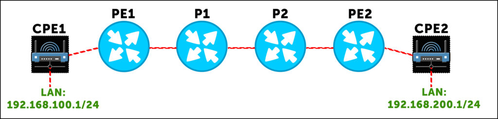
Host machine A, with IP address 192.168.100.5, wants to ping host B 192.168.200.5. So, host A makes a packet, and sends it to its default gateway, 192.168.100.1. This router looks up 192.168.200.5, finds a default route to PE1, and sends the packet out the WAN link towards PE1. At this stage, it’s a pure IP packet. But when it reaches PE1, the “magic” happens.
Our PE1 router does a lookup, and sees that it’s received a BGP route from PE2 (either directly or via a route reflector) that says “to get to 192.168.200.0/24 in this VPN, send the packet to me, and add label 69. That label will tell me which VRF this packet belongs to.” So, PE1 takes the packet, and adds service label 69. Which is of course the nicest label of them all.
So that’s cool – but now we have a question: how does PE1 get this labelled packet to PE2? That’s where our router now does a second lookup, and discovers that PE1 has a label-switched path to PE2, via P1. P1 will have already told PE1 “if you want to get to PE2, send the packet to me, and add label 420 to the packet.” This is the transport label.
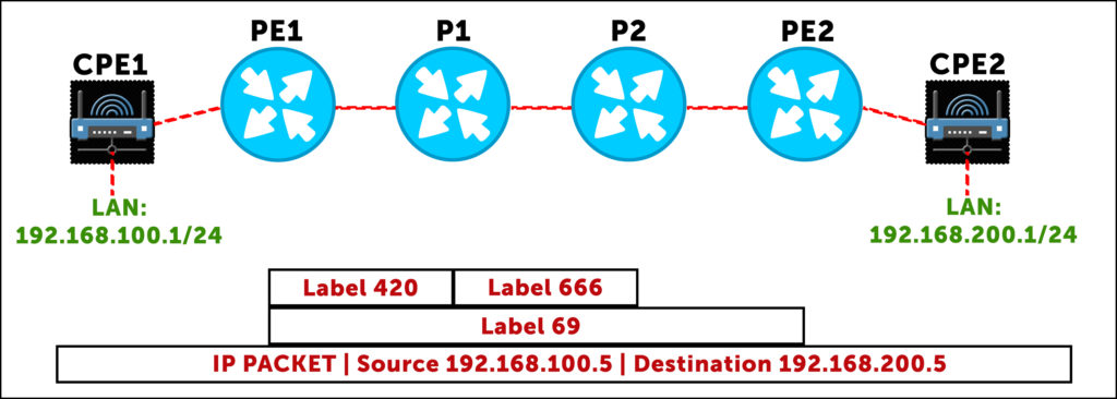
PE1 is now ready to send the packet, with a stack of two labels: an outer transport label of 420, and an inner VPN/service label of 69.
The packet reaches P1, which looks label 420 up in its LFIB (label forwarding information base). Notice that the inner label is of no interest to P1. The inner service label is only of interest to the PE router that’s actually dealing with the VPN. It’s only the outer label that’s of interest to P1. (In practice, the routers don’t really know the distinction between service and transport labels. All they know is “if you receive this label, do this thing with the packet”. The distinction between service and transport is really just for us.)
So, P1 does the lookup, and sees that if it receives label 420, swap it for label 666 and send it to P2.
The same thing happens again at P2: it looks up how to handle label 666. It sees that it should pop the label (ie get rid of the transport label altogether), and send the packet to PE2 with only its service label. Why does P2 pop the transport label? You’ll remember that routers usually perform penultimate hop popping – they remove the transport label when the next-hop is the actual end destination.
Finally, PE2 is left with a packet with one label: 69. So, PE2 looks in its own LFIB to see what it should do to a packet with label 69, and one of two things can happen:
- First, if the router has a label for each CPE link within the VRF, then PE2 doesn’t even need to look up the destination IP: it can just forward the packet directly to the CPE in question, because the label tells it which CPE the prefix belongs to.
- Alternatively, if we’re running a command like vrf-table-label, which creates one label for an entire VRF, then PE2 pops the label, does an IP lookup within the VRF in question, and then sends it to the relevant CPE router.
Either way, the packet will eventually reach CPE2, and then host 2. Wow, that journey was better than going on holiday!
Here’s that journey in graphical form, showing how the service label stays the same, while the transport label changes:
You probably instinctively knew the difference between service and transport labels, even if you haven’t thought about it quite so explicitly before. But knowing the difference is key to understand the interesting way that Option B works.
WHAT IS INTERPROVIDER OPTION B?
You’ll remember that Option A involved a lot of manual configuration on our Autonomous System Boundary Routers. (If you don’t remember, now is your last chance to go and read up on Option A before you carry on reading this!)
First, we had to manually configure every single customer VRF on the ASBRs that joined the two ISPs together. We then had to create many sub-interfaces between the ASBRs, put one sub-interface in each VRF, and then run multiple BGP sessions between the two ASBRs, one for each sub-interface. What a lot of overhead!
It’s important to understand what this ASBR-to-ASBR BGP session looks like in Option A. The two ASBRs aren’t using AFI 1 SAFI 128. In other words, they’re not advertising labelled IPv4 VPN prefixes. Remember, the two ASBRs treat each other as if they were customer routers, and we never (or at least, so rarely as to be never!) extend the MPLS piece of the VPN into the customer network. When we talk BGP from PE to CPE, we’re within the VRF itself, and as such we’re doing AFI 1 SAFI 1 – in other words, regular IPv4 unicast. As such, that’s exactly what we do in Option A between ASBR and ASBR: regular IPv4 unicast prefixes
Option B is different. In a moment we’re going to reconfigure our network, and as you’ll see, the difference with option B is that we actually advertise labelled VPN prefixes between the two autonomous systems! AFI 1, SAFI 128, from AS to AS. As such, we don’t need sub-interfaces, we don’t need multiple BGP sessions, and we don’t need a VRF per-customer on the ASBR.
There’s just two things we need to make Option B work. First, we only the one BGP peering, with the VPN-unicast sub-family enabled. I could give you a nice clean config to show you how it works, but instead we’re going to edit our previous topology together. In doing so, we’ll see some problems you can face – and how to fix them.
The second thing you’ll need to change is… actually, let me lead you down a path, and let’s see if you can work out the other thing we’ll need to do.
SOME CHANGES TO OUR TOPOLOGY
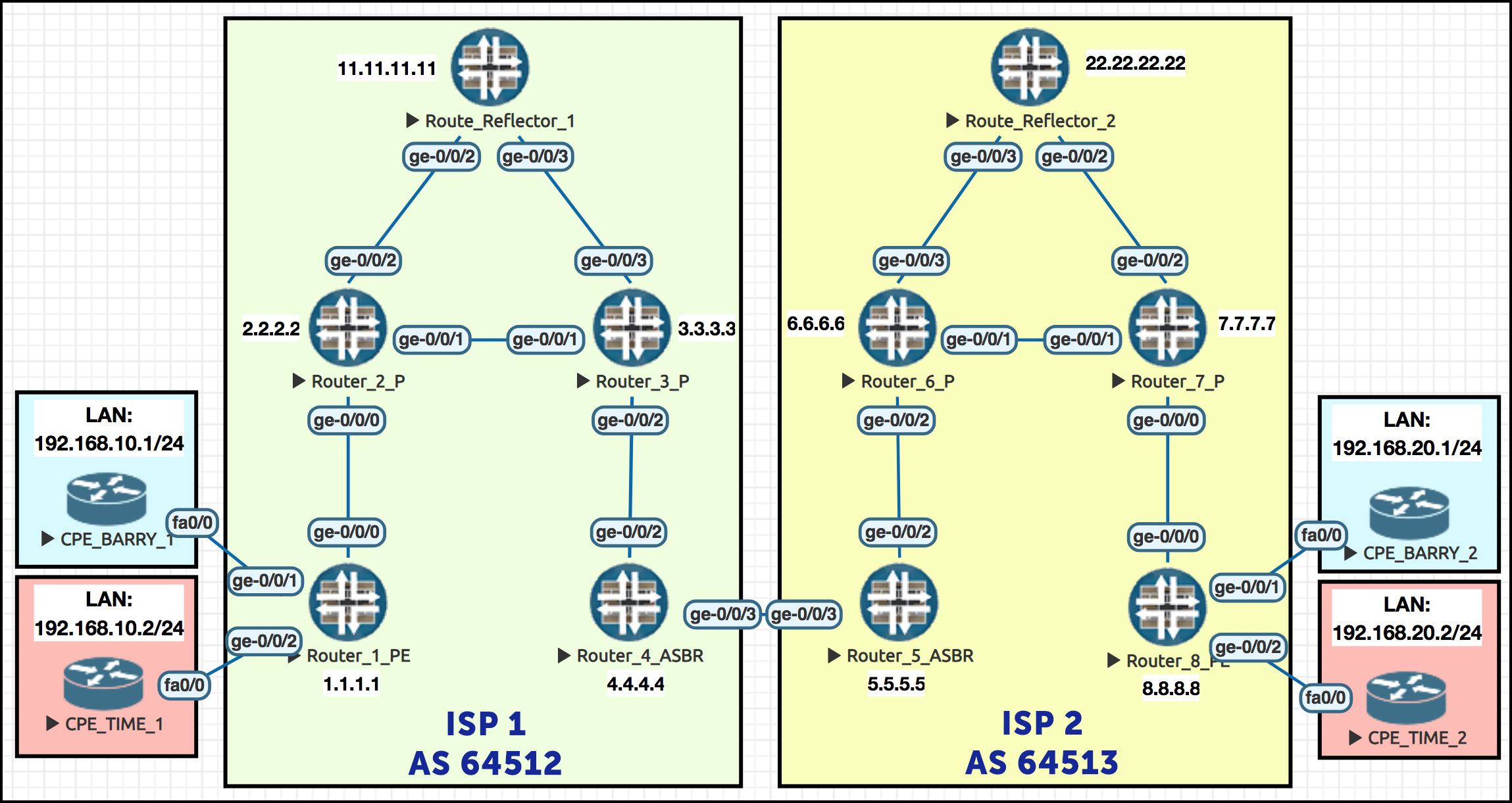
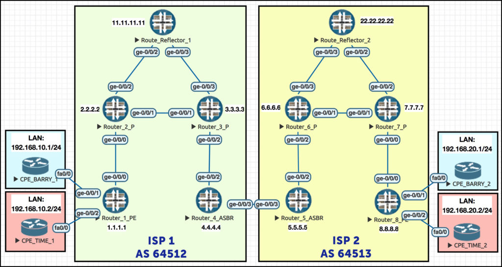
Remember this beautiful network? Gosh it makes my heart sing to see it! (Okay, one more chance: we explained the full philosophy of this topology in our Option A post. If this network confuses you, go give it a read!)
There’s a couple of changes I want to make. First of all, for the sake of simplicity in our Option A post we only used LDP in each AS. This time I’m going to edit ISP 2 so that it’s using RSVP. I could 100% keep using LDP, it doesn’t matter, but I want to make this change to emphasise to you the fact that ISP 1 and ISP 2 are two completely different autonomous systems, with separate IGPs, and separate label advertising protocols that don’t talk to each other. So: IS-IS and LDP in ISP 1, OSPF and RSVP in ISP 2.
Here’s my config change to Router 5 in ISP 2. I’m making a label-switched path to Router 8; I’m turning on MPLS and RSVP on my infrastructure interfaces; and because we’re running OSPF here, I’m also enabling OSPF’s traffic-engineering extensions. I also do the equivalent config on Router 8 for the LSP in the reverse direction. Here’s Router 5’s changes:
delete protocols ldp
set protocols rsvp interface ge-0/0/2.0
set protocols mpls interface ge-0/0/2.0
set protocol mpls label-switched-path PE5_to_PE8 to 8.8.8.8
set protocols ospf traffic-engineering
Routers 6 and 7 in ISP 2 have similar changes applied to them. The only difference is that the config for the label-switched path itself only happens on routers 5 and 8. Routers 6 and 7 receive the signals from 5 and 8 to build the path, and they obey, like good boys. Good boys! Who’s a good boy? It’s router 6!
So, for Routers 6 and 7 we just turn on protocols RSVP and MPLS. We already have “family mpls” on all the relevant interfaces from last time, so that’s all good.
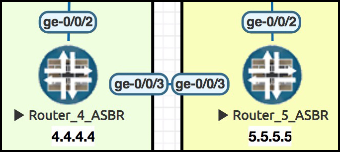
I’ll also remove all the BGP, VRFs and sub-interfaces on the link between ASBR routers 4 and 5, and just make a point-to-point link between them. I’ll just show you what I did to Router 4, but I’m doing the equivalent on Router 5 too:
delete routing-instances BARRYS_ICE_CREAM
delete routing-instances TIME_TRAVEL_INC
delete interfaces ge-0/0/3
set interfaces ge-0/0/3 unit 0 family mpls
set interfaces ge-0/0/3 unit 0 family inet address 10.10.45.4/24
SOME CHANGES TO ISP 2’s ROUTE REFLECTOR
I’ve also removed LDP on ISP 2’s route reflector – which means that my route reflector no longer has a label-switched path to routers 5 or 8. This causes an interesting problem: our previously-trustworthy route reflector no longer reflects the VPN prefixes!
When Router 8 passes its VPN routes to Reflector 2, they fail Reflector2’s “is the next-hop reachable” test. Sure, Reflector2 can get to Router 8 – via unicast IP. But can it get there via a labelled path? Are there any prefixes in inet.3 for Reflector2? No sir! As such, the prefixes aren’t passed on.
Luckily, we can fix this with one easy command:
set routing-options resolution rib bgp.l3vpn.0 resolution-ribs inet.0
This command tells Reflector2 that if there’s a prefix in bgp.l3vpn.0, resolve its next-hop in inet.0. We’ll definitely find Router 8 in inet.0!
That might be a bit confusing, so let’s break it down. Normally, when we need to look up the next-hop of a BGP VPN prefix, we resolve that next-hop in inet.3. This is because inet.3 contains all the other PEs in the network, and the transport label we should add to the packet before passing it to our physical next-hop.
Inet.0 also contains all the other PEs in the network – but without labels. So usually, resolving VPN next-hops in inet.0 wouldn’t work. Even if we did do this, the packet would go out of the router with only a service label on it. Our physical next-hop would receive the packet, look at the label, have no record of what to do with it, and drop it.
But in this specific case, we’re basically tricking our route reflector. Remember, this route reflector isn’t in the path of the traffic. It doesn’t matter whether the resolution would work or not. All that matters is that Reflector 2 thinks it will work. With this command we’ve tricked Reflector 2 into thinking that the prefixes pass the next-hop resolution test – and as such, it re-advertises the prefixes on throughout the network, which is exactly what we want to happen. For a route reflector that isn’t in the path of the traffic itself, this command is perfect.
(My guy Said van de Klundert talks about this command, and some other options to solve this out-of-path reflector problem, in this post. Give it a read!)
CONFIGURING OPTION B – AFI 1, SAFI 128
 Here’s a standard, simple BGP config, to make Routers 4 and 5 talk BGP. Again, we focus on Router 4:
set protocols bgp group TO_AS64513 type external
set protocols bgp group TO_AS64513 peer-as 64513
set protocols bgp group TO_AS64513 neighbor 10.10.45.5
Now, here’s the one line that makes the magic happen: we turn on AFI 1, SAFI 128. (Remember, turning this on turns off regular IPv4 unicast, so if you need it as well then you’ll want to configure that too! We don’t need it for this lab though.)
set protocols bgp group TO_AS64513 family inet-vpn unicast
And with that, our ISPs are sending prefixes to each other, right? They’re advertising each prefix for each VPN, with route targets and everything, right? Right?
Well, yes… but we’re not quite done yet.
Let’s see if Router 5 is advertising to Router 4:
root@Router5> show route advertising-protocol bgp 10.10.45.4

bgp.l3vpn.0: 4 destinations, 4 routes (4 active, 0 holddown, 0 hidden)
  Prefix                   Nexthop   MED   Lclpref   AS path
  8.8.8.8:1:172.16.20.0/30
*                          Self                      I
  8.8.8.8:1:192.168.20.0/24
*                          Self                      I
  8.8.8.8:2:172.16.20.4/30
*                          Self                      I
  8.8.8.8:2:192.168.20.0/24
*                          Self                      I
Great! Wow, it looks like it’s working! Okay, now let’s see whether Router 4 is advertising to Router 5:
root@Router4> show route advertising-protocol bgp 10.10.45.5

bgp.l3vpn.0: 8 destinations, 8 routes (8 active, 0 holddown, 0 hidden)
  Prefix                  Nexthop           MED   Lclpref   AS path
  1.1.1.1:1:172.16.10.0/30
*                         Not advertised                    I
  1.1.1.1:1:192.168.10.0/24
*                         Not advertised                    I
  1.1.1.1:2:172.16.10.4/30
*                         Not advertised                    I
  1.1.1.1:2:192.168.10.0/24
*                         Not advertised                    I
Oh that’s weird. What’s going on here? Let’s look at the extensive output:
root@Router4> show route advertising-protocol bgp 10.10.45.5 extensive

bgp.l3vpn.0: 8 destinations, 8 routes (8 active, 0 holddown, 0 hidden)
* 1.1.1.1:1:172.16.10.0/30 (1 entry, 1 announced)
 BGP group TO_AS64513 type External
     Route Distinguisher: 1.1.1.1:1
     BGP label allocation failure: protocols mpls not enabled on interface
     Nexthop: Not advertised
     Flags: Nexthop Change
     AS path: [64512] I
     Communities: target:64512:1
     {snip}
“Protocols MPLS not enabled on interface”. Interesting! On Router 5, “set protocols mpls” is already configured on our ge-0/0/2 interface – ie the interface that faces the rest of ISP 2 – because we’re running RSVP there. We didn’t previously turn it on for Router 4’s ge-0/0/2 interface, because LDP seems to work fine without it – but it turns out that in Option B, it’s needed!
So, let’s turn it on:
set protocols mpls interface ge-0/0/2.0
Did that fix it?
root@Router4> show route advertising-protocol bgp 10.10.45.5

bgp.l3vpn.0: 8 destinations, 8 routes (8 active, 0 holddown, 0 hidden)
  Prefix                  Nexthop   MED   Lclpref   AS path
  1.1.1.1:1:172.16.10.0/30
*                         Self                      I
  {snip}
Hooray! We see that R4 is making itself the next-hop when it advertises the prefix to R5, because we’re passing from iBGP to eBGP.
We’re also successfully receiving prefixes from Router 5. Let’s hop over to Router 5 and check that it’s receiving prefixes from Router 4:
root@Router5> show route receive-protoocol bgp 10.10.45.4 table bgp.l3vpn.0

bgp.l3vpn.0: 8 destinations, 8 routes (8 active, 0 holddown, 0 hidden)
  Prefix                Nexthop     MED   Lclpref   AS path
1.1.1.1:1:172.16.10.0/30
*                       10.10.45.4                  64512 I
  {snip}
Great! And I trust that Router 5 is passing this on to Reflector 2, right?
root@Router5> show route advertising-protocol bgp 22.22.22.22

bgp.l3vpn.0: 8 destinations, 8 routes (8 active, 0 holddown, 0 hidden)
  Prefix                Nexthop          MED   Lclpref   AS path
1.1.1.1:1:172.16.10.0/30
*                       Not advertised         100       64512 I
 {snip}
Gah! There’s always a hurdle! Okay, what’s the problem this time:
root@Router5> show route advertising-protocol bgp 22.22.22.22 extensive

bgp.l3vpn.0: 8 destinations, 8 routes (8 active, 0 holddown, 0 hidden)
* 1.1.1.1:1:172.16.10.0/30 (1 entry, 1 announced)
BGP group AS64513 type Internal
    Route Distinguisher: 1.1.1.1:1
    BGP label allocation failure: protocols mpls not enabled on interface
    Nexthop: Not advertised
    Flags: Nexthop Change
    Localpref: 100
    AS path: [64513] 64512 I
    Communities: target:64512:1
    {snip}
Wait a second – not enabled? Yes it is. We’re running RSVP. RSVP wouldn’t work if we hadn’t enabled it.
Here’s the twist: this time our output isn’t talking about ge-0/0/2, the interface that connects up to R6, and on to Reflector 2.
No, instead it’s talking about ge-0/0/3, our interface that connects to R4 in ISP 1. The extensive output doesn’t explicitly say what interface needs “protocols mpls” to be turned on, but you can always assume it’s the interface that R5 learnt the prefix from. In other words, if you’re not advertising the prefix properly, take a look at the interface you originally received it from.
Let’s add this command to Routers 4 and 5:
set protocols mpls interface ge-0/0/3.0
Did it work?
root@Router5> show route advertising-protocol bgp 22.22.22.22

bgp.l3vpn.0: 8 destinations, 8 routes (8 active, 0 holddown, 0 hidden)
  Prefix                Nexthop      MED   Lclpref   AS path
1.1.1.1:1:172.16.10.0/30
*                       Self               100       64512 I
  {snip}
Now that’s curious – it did indeed work, but isn’t it interesting that Router 5 made itself the next-hop for this route, without us even having to ask it to! Normally when a router learns a prefix by eBGP and advertises it into iBP, it doesn’t alter the next hop. But it seems that SAFI 128 is an exception!
CONFIGURING OPTION B – THE SECOND SECRET BIT
Just a quick reminder of the topology, to save you scrolling:
So, Router 5 successfully advertises this prefix to its route reflector. Reflector 2 picks up this prefix, and advertises it to Router 8:
root@Reflector2> show route advertising-protocol bgp 8.8.8.8

bgp.l3vpn.0: 8 destinations, 8 routes (8 active, 0 holddown, 0 hidden)
  Prefix                Nexthop      MED   Lclpref   AS path
1.1.1.1:1:172.16.10.0/30
*                       5.5.5.5            100       64512 I
  {snip}
And finally Router 8 picks up the advertisement, and…. oh wait:
root@Router8> show route receive-protocol bgp 22.22.22.22 bgp.l3vpn.0
  error: could not resolve name: bgp.l3vpn.0: bgp.l3vpn.0
You’ll see this error when there’s nothing in bgp.l3vpn.0. If there’s nothing in there, the table doesn’t exist.
Now that’s strange. Why isn’t anything in there? Let’s take a look once again at what Reflector 2 is advertising:
root@Reflector2> show route advertising-protocol bgp 8.8.8.8 extensive

bgp.l3vpn.0: 8 destinations, 8 routes (8 active, 0 holddown, 0 hidden)
* 1.1.1.1:1:172.16.10.0/30 (1 entry, 1 announced)
 BGP group AS64513 type Internal
     Route Distinguisher: 1.1.1.1:1
     VPN Label: 300272
     Nexthop: 5.5.5.5
     Localpref: 100
     AS path: [64513] 64512 I
     Communities: target:64512:1
     Cluster ID: 22.22.22.22
     Originator ID: 5.5.5.5
     {snip}
Aah, of course – we got so excited to lab everything up, we forgot about the community! The reason Router 8 isn’t importing the prefix is because the prefix has ISP 1’s target community for this customer. Router 8 is in ISP 2. The prefix is totally missing the target community Router 8 needs!
In ISP 1, Barry’s Ice Cream has the target community target:64512:1. But in ISP 2, it’s different – it’s target:64513:1. And to understand why this prefix has been completely discarded by R8, as opposed to R8 just hiding it, we turn to Juniper themselves:
“VPN route processing differs from normal BGP route processing in one way. In BGP, routes are accepted if they are not explicitly rejected by import policy. However, because many more VPN routes are expected, the Junos OS does not accept (and hence store) VPN routes unless the route matches at least one VRF import policy. If no VRF import policy explicitly accepts the route, it is discarded and not even stored in the bgp.l3vpn.0 table. As a result, if a VPN change occurs on a PE router—such as adding a new VRF table or changing a VRF import policy—the PE router sends a BGP route refresh message to the other PE routers (or to the route reflector if this is part of the VPN topology) to retrieve all VPN routes so they can be reevaluated to determine whether they should be kept or discarded.”
Well, there we have it. A bit annoying in a lab, but pretty understandable in the real world!
So, how do we fix it?
DEALING WITH DIFFERENT TARGET COMMUNITIES BETWEEN ISPs
If the two ISPs have a good trust relationship, it can be nice to just leave the communities as they are, and add them to your respective VRFs. This gives you a quick way of identifying which prefixes came from the other ISP. Let’s do that on Router 8. To import multiple targets into a VRF, we have to make a policy saying which communities we want to import/export, and then refer to that policy in the VRF.
We create this policy on Router 8, which I’ll put in hierarchy format here to make it easier to read:
root@Router8> show configuration policy-options
policy-statement TARGET_EXPORT_BARRYS_ICE_CREAM {
    term ADD_CORRECT_COMMUNITY {
        then {
            community add TARGET_AS64513_BARRYS_ICE_CREAM;
            accept;
} }
    term REJECT {
        then reject;
} }
policy-statement TARGET_IMPORT_BARRYS_ICE_CREAM {
    term ACCEPT_CORRECT_COMMUNITY {
        from community [ TARGET_AS64512_BARRYS_ICE_CREAM TARGET_AS64513_BARRYS_ICE_CREAM ];
        then accept;
}
    term REJECT {
        then reject;
} }
community TARGET_AS64512_BARRYS_ICE_CREAM members target:64512:1;
community TARGET_AS64513_BARRYS_ICE_CREAM members target:64513:1;
We then get rid of the previous single route-target in this customer’s VRF on Router 8, and add the policy instead:
delete routing-instances BARRYS_ICE_CREAM target target:64513:1
set routing-instances BARRYS_ICE_CREAM vrf-import TARGET_IMPORT_BARRYS_ICE_CREAM
set routing-instances BARRYS_ICE_CREAM vrf-export TARGET_EXPORT_BARRYS_ICE_CREAM
And then, suddenly, we see something magical: the prefix is finally accepted by Router 8.
root@Router8> show route receive-protocol bgp 22.22.22.22 table bgp.l3vpn.0

bgp.l3vpn.0: 2 destinations, 2 routes (2 active, 0 holddown, 0 hidden)
  Prefix                  Nexthop   MED   Lclpref   AS path
  1.1.1.1:1:172.16.10.0/30
*                         5.5.5.5   100             64512 I
  1.1.1.1:1:192.168.10.0/24
*                         5.5.5.5   100             64512 I
This is great when the two ISPs have that trust. However, sometimes we might not want to exchange communities with the other ISP. Perhaps they clash between ISPs, or perhaps they’re super top-secret.
Luckily, we can make a policy to strip the community as it comes into ISP 1 and replace it with another community as we advertise it throughout our own domain.
Let’s do it on Router 4, to see what it looks like. After creating the same named communities as above, we add a policy like this on Router 4:
root@Router4> show configuration policy-options
policy-statement AS64513_COMMUNITY_REWRITE {
    term BARRYS_ICE_CREAM {
        from community TARGET_AS64513_BARRYS_ICE_CREAM;
        then {
            community delete TARGET_AS64513_BARRYS_ICE_CREAM;
            community add TARGET_AS64512_BARRYS_ICE_CREAM;
            accept;
        } } }
Let’s put this policy on the BGP peering to Router 5:
set protocols bgp group TO_AS64513 import AS64513_COMMUNITY_REWRITE
Did it work? Let’s see what Router 4 advertises to its own route reflector
root@Router4> show route advertising-protocol bgp 11.11.11.11 extensive

bgp.l3vpn.0: 8 destinations, 8 routes (8 active, 0 holddown, 0 hidden)
* 8.8.8.8:1:172.16.20.0/30 (1 entry, 1 announced)
 BGP group AS64512 type Internal
     Route Distinguisher: 8.8.8.8:1
     VPN Label: 299952
     Nexthop: Self
     Flags: Nexthop Change
     Localpref: 100
     AS path: [64512] 64513 I
     Communities: target:64512:1
You bet your life it worked!! Can Barry’s CPE1 finally ping Barry’s CPE2?
CPE_BARRY_1>ping 192.168.20.1

Type escape sequence to abort.
Sending 5, 100-byte ICMP Echos to 192.168.20.1, timeout is 2 seconds:
!!!!!
Success rate is 100 percent (5/5), round-trip min/avg/max = 88/120/148 ms
Niiiiiiice. Nice! #Nice.
SOME FINAL COMMENTS ON THE LABELS BETWEEN R4 AND R5
Earlier on we saw a picture that explained what the different labels look like as a packet goes on its merry way. Before we finish this post, let’s have a think about the flow of traffic from ISP 1 to ISP 2.
In Option A, there’s no labels between our ASBRs. The packet is pure IP. Remember, they treat each other as CPEs. The MPLS piece of the VPN stops at Router 4, and starts again at Router 5.
In Option B, we do indeed have labels. However, what’s interesting is that there’s only the one label! One service label per-prefix per-VPN. No transport label. Why is that?
Well, partly it’s because our routers are directly connected, so a transport label isn’t really needed. But even then, remember that we’re not running LDP or RSVP between the providers. Router 4’s inet.3 table has no knowledge of any prefixes in ISP 2, including Router 5. Indeed, Router 4 isn’t even aware of the VRFs its passing between ISPs!
Routers 4 and 5 are pure transit. Basically, router 4 is saying to Router 5! “I know about 192.160.10.0/24 with this route target! I don’t know what that means, but I do know I can get to it. So, if it means something to you, feel free to throw packets my way. Just make sure you put label X on it, so I know where to send it to.”
In a way, you could argue that this one label serves the dual purposes of both service AND transport header! Gosh, isn’t philosophy fun.
Make sure this concept makes sense to you. It might seem like trivia right now – but in our next post, when we look at Interprovider Option C, it will turn out that this knowledge is vitally important!
DOWNLOAD ALL ROUTER CONFIGS HERE!
Here you go! Take a look, put it on routers yourself, and get hands-on with the good stuff. In that text file you’ll find the config for all ten Juniper routers in this lab. Merry Christmas!
THAT’S IT!
We took a real deep dive there! But actually, it’s not too hard really. I just wanted to show you some of the things that can go wrong, and a few gotchas to bear in mind. For example, if you’re only running LDP, you might not think to turn on “family mpls” on an interface that faces another ISP! Basically: turn on the inet-vpn unicast family, and plan how you want to deal with different communities. Do those two things, and you’re golden!
Next week (don’t hold me to that, I have a lot of Super Mario to catch up on) we’ll be looking at the third way to extend an MPLS VPN between two ISPs. It’s called Option C, and it’s extremely cool. We’re going to have a blast! Click here to read it!
If you’re on Mastodon, follow me to find out when I make new posts. (2024 edit: I’m also on BlueSky nowadays too. I was once on Twitter, but I’ve given up on it, on account of… well, I don’t need to finish that sentence, do I.)
And of course, if you enjoyed this post, I’d love you to share it on your favourite social media. Or maybe print it out and hand it to people in the street? Or, maybe don’t. It’s up to you!
And if you fancy some more learning, take a look through my other posts. I’ve got plenty of cool new networking knowledge for you on this website, especially covering Juniper tech and service provider goodness.
It’s all free for you, although I’ll never say no to a donation. This website is 100% a non-profit endeavour, in fact it costs me money to run. I don’t mind that one bit, but it would be cool if I could break even on the web hosting, and the licenses I buy to bring you this sweet sweet content.


Hello
I had this setup on a multi-vendor scenario where the ASBRs were Cisco and Juniper respectively and only got it working after enabling the BGP-LU between them (my config on https://github.com/basondole/mpls/blob/master/MPLS%20Inter%20AS%20Option%20B%20IPv4%20VPNs.md). In your example I see there was no need for BGP-LU between the ASBR. Have you tried this in a multivendor situation?
Hi Paul,
First of all, sorry for the truly massive delay in replying!
I think the link might have changed now, is this the post you were referring to? https://github.com/basondole/mpls/blob/master/Inter%20AS%20Option%20B%20IPv4%20VPNs.md
I’m genuinely confused about why you’d need BGP-LU for it to work. Option B shouldn’t require labelled-unicast at all. The only thing that should matter is exchanging labelled vpn-unicast prefixes between the ASBRs. What happens when you do this between two Cisco boxes? Do you need labelled-unicast between them? I wonder if it’s a requirement for some reason, but I can’t see why it would be. The only reason I can think of is that maybe the Cisco won’t accept the VPN prefix unless it has a labelled path to the sender, and so by turning on BGP-LU you’re making one. But I can’t see why that would be necessary, because the whole point is that each individual VPN label has significance to the ASBR. You push the traffic straight to the ASBR with the single VPN label, the ASBR looks up that label, and then builds the new labelled path and new VPN label acccordingly.
So that’s a long way of saying: lol dunno. I don’t have enough Cisco experience to say. For what it’s worth, I looked in MPLS In The SDN Era, which is a book that specialises in Juniper-to-Cisco MPLS interoperability issues, and they also don’t use labelled-unicast on their Option B config, so it’s at least not a requirement in IOS-XR.
Just want to say how brillaint this is !!! using this to study for my JNCIP-SP , thanks
Brilliant! Thank you Simon, all the best of luck with your studies!
Excellent, Thanks for brilliant info.